
- Stress determination using an elastic-plastic material model
- Design of masonry disc structures for compression and shear on the building model or single model
- Automatic determination of stiffness of a wall-slab hinge
- An extensive material database for almost all stone-mortar combinations available on the Austrian market (the product range is continuously being expanded, for other countries as well)
- Automatic determination of material values according to Eurocode 6 (ÖN EN 1996‑X)
- Option to create pushover analysis
_(2).png?mw=640&hash=0414bfe44045fc798e3774a0173332ca37424418)
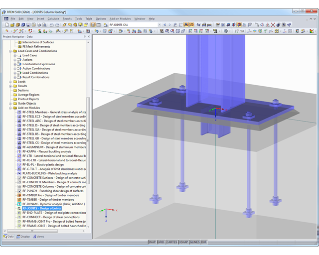
General
- Beam to Column joint category: connection possible as joint of the beam to the column flange as well as joint of the column to the girder flange
- Beam to Beam joint category: design of beam joints as both moment-resisting end plate connections and rigid splice connections possible
- Automatic export of model and load data possible from RFEM or RSTAB
- Bolt sizes from M12 to M36 with strength grades 4.6, 4.8, 5.6, 5.8, 6.8, 8.8, and 10.9 as long as the strength grades are available in the selected National Annex
- Almost any bolt spacing and edge distances (a check of the allowable distances is performed)
- Beam strengthening with tapers or stiffeners on the top and bottom surfaces
- End plate connection with and without overlap
- Connection with pure bending stress, pure normal force load (tension joint), or combination of normal force and bending possible
- Calculation of connection stiffnesses and check if a hinged, semi-rigid, or rigid connection exists
End plate connection in a beam-column setup
- Joint beams or columns can be stiffened with tapers on one side or with stiffeners to one or both sides
- Wide range of possible stiffeners of the connection (for example, complete or incomplete web stiffeners)
- Up to ten horizontal and four vertical bolts possible
- Connected object possible as constant or tapered I-section
- Designs:
- Ultimate limit state of the connected beam (such as shear or tension resistance of the web plate)
- Ultimate limit state of the end plate at the beam (for example, T-stub under tensile stress)
- Ultimate limit state of the welds at the end plate
- Ultimate limit state of the column in the area of the connection (for example, column flange under bending – T-stub)
- All designs are performed according to EN 1993-1-8 and EN 1993-1-1
Moment-resisting end plate joint
- Two or four vertical and up to 10 horizontal bolt rows
- Joint beams can be stiffened with tapers on one side or with stiffeners to one or both sides
- Connected objects are possible as constant or tapered I-sections
- Designs:
- Ultimate limit state of the connected beams (such as shear or tension resistance of the web plates)
- Ultimate limit state of the end plates at the beam (for example, T-stub under tensile stress)
- Ultimate limit state of the welds at the end plates
- Ultimate limit state of the bolts in the end plate (combination of tension and shear)
Rigid splice plate connection
- For the flange plate connection, up to ten bolt rows one behind the other possible
- For the web plate connection, up to ten bolt rows possible each in vertical and horizontal directions
- Material of the cleat can be different from the one of the beams
- Designs:
- Ultimate limit state of the joint beams (for example, net cross-section in the tension area)
- Ultimate limit state of the cleat plates (for example, net cross-section under tensile stress)
- Ultimate limit state of the single bolts and the bolt groups (for example, shear resistance design of the single bolt)
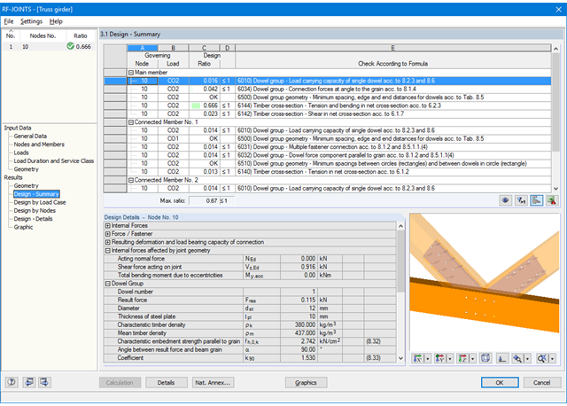
At first, the governing joint designs are arranged in groups and displayed with the basic geometry of the joint in the first result window. In the other result windows, you can see all fundamental design details.
Dimensions, material properties, and welds important for the connection construction are displayed immediately and can be printed directly. Similarly, export to DXF-file is enabled. The connections can be visualized in the RF-/JOINTS Timber - Timber to Timber module as well as in RFEM/RSTAB.
All graphics can be included in the RFEM/RSTAB printout report or printed directly. Due to the scaled output, an optimal visual check is possible as early as in the design phase.
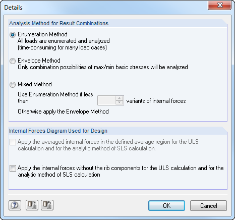
After opening the program, you can define the standard and method according to which the design is performed. The ultimate and serviceability limit states can be designed according to the linear and nonlinear calculation methods. Load cases, load combinations or result combinations are then assigned to different calculation types. In other input windows, you can define materials and cross‑sections. In addition, it is possible to assign parameters for creep and shrinkage. Creep and shrinkage coefficients are directly adjusted, depending on the age of the concrete.
Support geometry is determined by means of design‑relevant data such as support widths and types (direct, monolithic, end, or intermediate support) and redistribution of moments as well as shear force and moment reduction. CONCRETE recognizes the support types from the RSTAB model automatically.
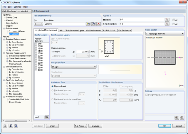
A segmented window includes the specific reinforcement data such as diameters, the concrete cover and curtailment type of reinforcements, number of layers, cutting ability of links, and the anchorage type. In the case of the fire resistance design, it is necessary to define the fire resistance class, the fire‑related material properties, and the cross-section side exposed to fire. Members and sets of members can be summarized in special 'reinforcement groups', each with different design parameters.
You can adjust the limit value of the maximum crack width in the case of crack width analysis. The geometry of tapers is to be determined additionally for the reinforcement.
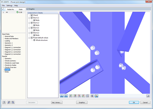
At first, the governing joint designs are arranged in groups and displayed with the basic geometry of the joint in the first result window. In the other result tables, you can see all fundamental design details such as the bearing resistance, shearing, sliding, and others.
Dimensions, material properties, and welds important for the connection construction are displayed immediately and can be printed directly. It is possible to visualize the connections in RF-/JOINTS Steel - Tower or in the RFEM/RSTAB model.
All graphics can be included in the RFEM/RSTAB printout report or printed directly. Due to the scaled output, an optimal visual check is possible as early as in the design phase.
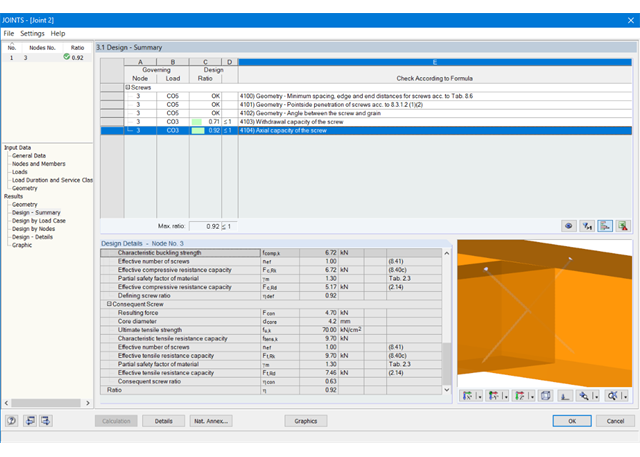
At first, the governing joint designs are arranged in groups and displayed with the basic geometry of the joint in the first result window. In the other result windows, you can see all fundamental design details.
Dimensions, material properties, and welds important for the connection construction are displayed immediately and can be printed directly. Similarly, export to DXF-file is enabled. It is possible to visualize the connections in RF‑/JOINTS Timber - Steel to Timber or in the RFEM/RSTAB model.
All graphics can be included in the RFEM/RSTAB printout report or printed directly. Due to the scaled output, an optimal visual check is possible as early as in the design phase.
At first, the governing joint designs are arranged in groups and displayed with the basic geometry of the joint in the first result window. In the other result tables, you can see all fundamental design details such as the load-carrying capacity of anchors, stresses in welds, and others.
Dimensions, material specifications, and welds that are important for the construction of the connection are visible immediately and can be printed out. It is possible to visualize the connections in RF-/JOINTS Steel - Column Base or in the RFEM/RSTAB model.
All graphics can be included in the RFEM/RSTAB printout report or printed directly. Due to the scaled output, an optimal visual check is possible as early as in the design phase.
In order to facilitate the data input, surfaces, members, sets of members, materials, surface thicknesses, and cross-sections are preset in RFEM. It is possible to select the elements graphically using the [Select] function. The program provides access to the global material and section libraries. Load cases, load combinations, and result combinations can be combined in various design cases. You can enter all geometric and standard-specific reinforcement settings for the reinforced concrete design in a segmented window. The geometry entries in both RF‑CONCRETE modules differ from each other.
- In the RF-CONCRETE Members add-on module, for example, This includes, for example, specifications for the curtailment of rebars, number of layers, cutting ability of links, and anchorage type. For the fire resistance design of reinforced concrete members, you have to define the fire resistance class, the fire‑related material properties, and the cross‑section sides exposed to fire.
- In the RF‑CONCRETE Surfaces add‑on module, it is necessary to specify, for example, the concrete cover, the reinforcement direction, the minimum and the maximum reinforcement, the basic reinforcement to be applied, or the designed longitudinal reinforcement, as well as the rebar diameter.
Surfaces or members can be summarized in special "reinforcement groups", each defined by different design parameters. This way, it is possible to efficiently calculate alternative designs with different boundary conditions or modified cross‑sections.
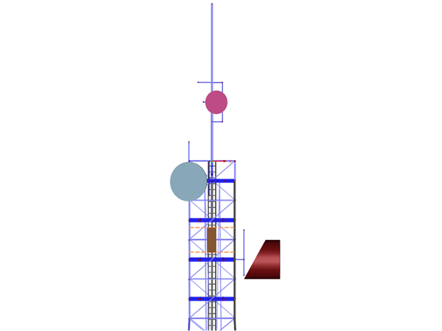
- Generation of inside and outside platforms using the library, including parameterized models
- Tubular extension and antenna bracket libraries as 2D and 3D structures
- Antenna groups sorted by mobile network operator
- Antenna library including parabolic, lense, shell, compact, and cuboidal antennas
- Parameterized input of inner and cable ducts as well as ladders with interactive graphics