
The design of cold-formed steel members according to the AISI S100-16 / CSA S136-16 is available in RFEM 6. Design can be accessed by selecting “AISC 360” or “CSA S16” as the standard in the Steel Design Add-on. “AISI S100” or “CSA S136” is then automatically selected for the cold-formed design.
RFEM applies the Direct Strength Method (DSM) to calculate the elastic buckling load of the member. The Direct Strength Method offers two types of solutions, numerical (Finite Strip Method) and analytical (Specification). The FSM signature curve and buckling shapes can be viewed under Sections.

Various design parameters of the cross-sections can be adjusted in the serviceability limit state configuration. The applied cross-section condition for the deformation and crack width analysis can be controlled there.
For this, the following settings can be activated:
- Crack state calculated from associated load
- Crack state determined as an envelope from all SLS design situations
- Cracked state of cross-section - independent of load
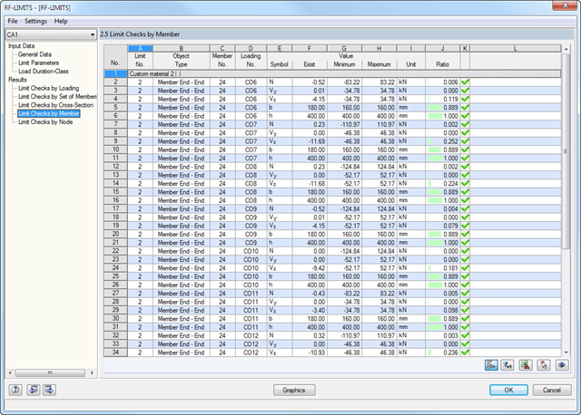
First, the governing design checks of the connection for the respective load case, and load combination, or result combination are displayed. In addition, it is possible to display results separately for sets of members, surfaces, cross-section, members, nodes, and nodal supports.
- You can use a filter to further reduce the displayed results and thus present them in a clearer way.
- Cross-sectional area A
- Shear areas Ay und Az with or without transversal shear
- Centroid position yS, zS
- moments of area 2 degrees Iy, Iz, Iyz, Iu, Iv, Ip
- Inclination of principal axes α
- Radii of gyration iy, iz, iyz, iu, iv, ip
- Torsional constant J
- Cross-section weight G and cross-section perimeter U
- Location of the shear center yM, zM
- Warping constants Iω,S, Iω,M
- Max/min cross-section moduli Sy, Sz, Su, Sv und St
- Plastic cross-section moduli Zy,pl, Zz,pl, Zu,pl, Zv,pl
- Stress function according to Prandtl φ
- Derivation of φ with respect to y and z
- Warping ω
- Cross-section modeling using surfaces, openings, and point areas (reinforcements) limited by polygons
- Automatic or individual arrangement of stress points
- Extensible library of concrete, steel, and reinforcing steel materials
- Cross-section properties of reinforced concrete and composite cross-sections
- Stress analysis with yield hypothesis according to von Mises and Tresca
- Reinforced concrete design according to:
-
 DIN 1045-1:2008-08
 -
DIN 1045:1988-07
-
 ÖNORM B 4700: 2001-06-01
 -
 EN 1992-1-1:2004
-
- For the design according to EN 1992-1-1:2004, the following National Annexes are available:
-
DIN EN 1992-1-1/NA:2013-04 (Germany)
-
 NEN-EN 1992-1-1/NA:2011-11 (Netherlands)
 -
 CSN EN 1992-1-1/NA:2006-11 (Czech Republic)
 -
ÖNORM B 1992-1-1:2011-12 (Austria)
-
 UNE EN 1992-1-1/NA:2010-11 (Spain)
 -
 EN 1992-1-1 DK NA:2007-11 (Denmark)
 -
 SIST EN 1992-1-1:2005/A101:2006 (Slovenia)
 -
 NF EN 1992-1-1/NA:2007-03 (France)
 -
 STN EN 1992-1-1/NA:2008-06 (Slovakia)
 -
 SFS EN 1992-1-1/NA:2007-10 (Finland)
 -
 BS EN 1992-1-1:2004 (United Kingdom)
 -
 SS EN 1992-1-1/NA:2008-06 (Singapore)
 -
 NP EN 1992-1-1/NA:2010-02 (Portugal)
 -
 UNI EN 1992-1-1/NA:2007-07 (Italy)
 -
 SS EN 1992-1-1/NA:2008 (Sweden)
 -
 PN EN 1992-1-1/NA:2008-04 (Poland)
 -
 NBN EN 1992-1-1 ANB:2010 (Belgium)
 -
 NA to CYS EN 1992-1-1:2004/NA:2009 (Cyprus)
 -
 BDS EN 1992-1-1:2005/NA:2011 (Bulgaria)
 -
 LST EN 1992-1-1:2005/NA:2011 (Lithuania)
 -
 SR EN 1992-1-1:2004/NA:2008 (Romania)
-
- In addition to the National Annexes (NA) listed above, you can also define a specific NA, applying user‑defined limit values and parameters.
- Reinforced concrete design for stress-strain distribution, available safety, or direct design
- Results of reinforcement list and total reinforcement area
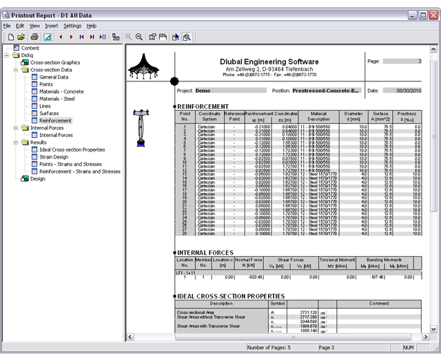
- Printout report with option to print a short form
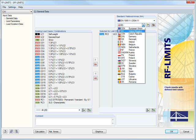
After selecting the loads required for the design and, if necessary, the desired standard for the design, you can define the limit loads in Window 1.2 Limit Parameters. In addition to the manufacturers listed in the limit library, it is possible to add user-defined entries.
After selecting all limit elements for the design, you can optionally define the load duration class (LDC). However, this module window is available only for timber fastener design according to EN 1995-1-1 or DIN 1052.
All results can be evaluated and visualized in an appealing numerical and graphical form. Selection functions facilitate the targeted evaluation.
The printout report corresponds to the high standards of RFEM and -rstab RSTAB. Modifications are updated automatically. Furthermore, you can print the reduced report in a short form, including all relevant data and a user-defined cross-section graphic.
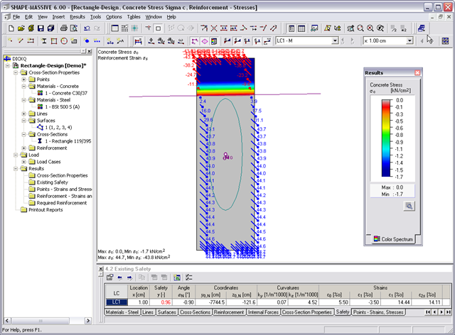
- Stresses σ and strains ε of concrete and reinforcement without considering concrete tensile strength (state II)
- Ultimate limit state design (existing safety) or design of defined internal forces
- Location of the neutral axis α0, y0,N, z0,N
- Curvatures ky, kz
- strain in the zero point ε0 and governing strains at the compression edge ε1 and at the tension edge ε2
- Governing steel strain ε2s
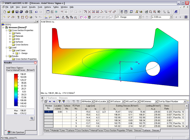
- Normal stresses σx due to axial force and bending
- Shear stresses τ due to shear force and torsion
- Equivalent stresses σv compared to limit stress
- Stress ratios related to equivalent stresses
- Normal stress σx due to unit axial force N
- Shear stress τ due to unit shear forces Vy, Vz, Vu, Vv
- Normal stress σx due to unit momentsMy, Mz, Mu, Mv
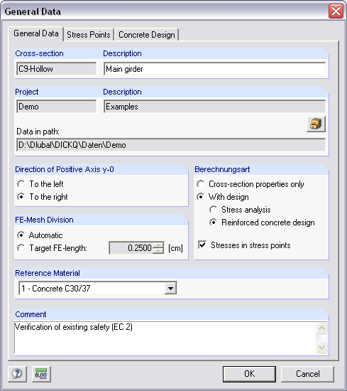
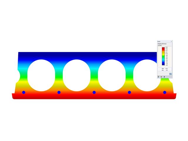
It is possible to freely model a cross-section using surfaces limited by polygonal lines, including openings and point areas (reinforcements). Alternatively, you can use the DXF interface to import the geometry. An extensive material library facilitates the modeling of composite cross-sections.
Definition of limit diameters and priorities allows for a curtailment of reinforcements. In addition, you can consider the respective concrete covers and prestresses.