
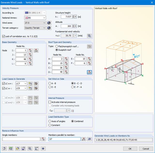
Wind loads can be automatically generated as member loads or area loads on the following structural components (optional with internal pressure for open buildings):
- Vertical walls
- Flat roofs
- Monopitch roofs
- Duopitch/troughed roofs
- Vertical walls with roof
The following standards are available:
-
 EN 1991-1-3 (incl. National Annexes)
 -
 DIN 1055-4
 -
 CTE DB-SE-AE
 -
 ASCE/SEI 7-16
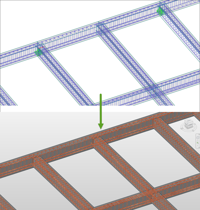
The reinforcement proposal from RF-/CONCRETE Members can be exported to Revit. The rectangular and circular cross-sections are currently supported.
The reinforcement bars can be modified retroactively in Revit.
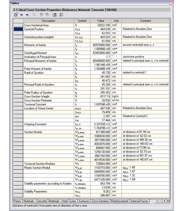
- Cross-sectional area A
- Shear areas Ay und Az with or without transversal shear
- Centroid position yS, zS
- moments of area 2 degrees Iy, Iz, Iyz, Iu, Iv, Ip
- Inclination of principal axes α
- Radii of gyration iy, iz, iyz, iu, iv, ip
- Torsional constant J
- Cross-section weight G and cross-section perimeter U
- Location of the shear center yM, zM
- Warping constants Iω,S, Iω,M
- Max/min cross-section moduli Sy, Sz, Su, Sv und St
- Plastic cross-section moduli Zy,pl, Zz,pl, Zu,pl, Zv,pl
- Stress function according to Prandtl φ
- Derivation of φ with respect to y and z
- Warping ω
Wind loads can be automatically generated as member loads on the following structural components (optional with internal pressure for open buildings):
- Vertical walls
- Flat roofs
- Monopitch roofs
- Duopitch/troughed roofs
- Vertical walls with roof
The following standards are available:
-
EN 1991-1-3 (incl. National Annexes)
-
DIN 1055-4
-
CTE DB-SE-AE
-
ASCE/SEI 7-16
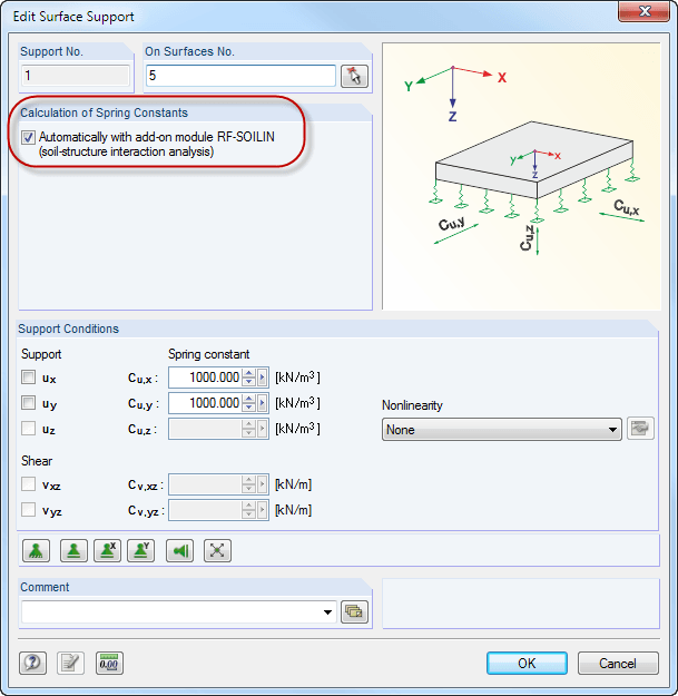
Elastic foundation coefficients are calculated according to the non-linear iterative method. The module determines elastic foundation coefficients for each individual element. They are dependent on the deformation.
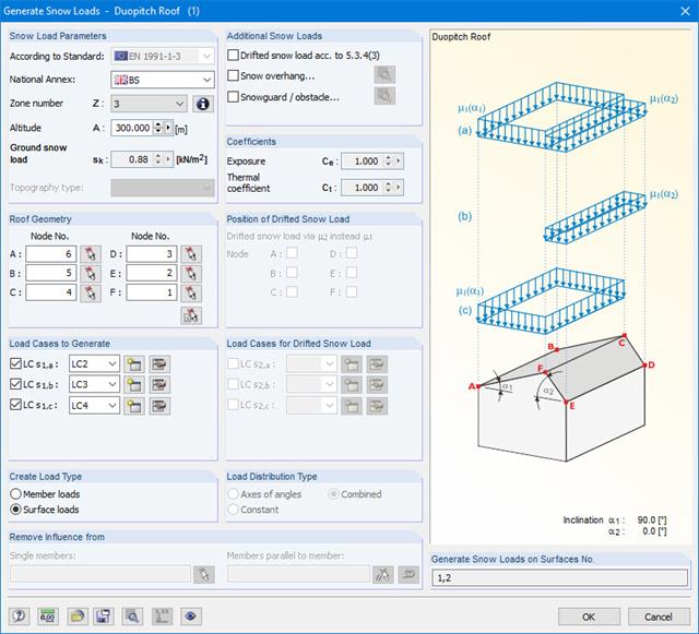
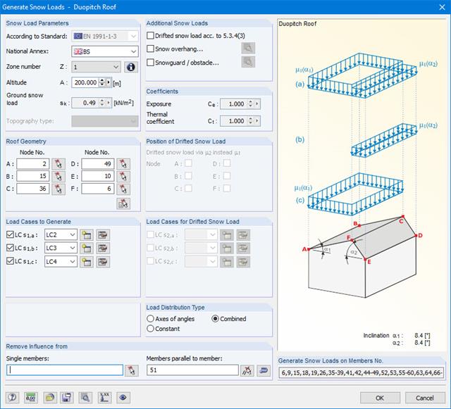
The snow load generator can generate snow loads as member loads or surface loads.
Additional snow loads such as drifted snow loads, snow overhangs, and snow guards can be taken into account as well.
The following standards are available:
-
EN 1991-1-3 (incl. National Annexes)
-
DIN 1055-5
-
CTE DB-SE-AE
-
ASCE/SEI 7-16

In the Steel Joint add-on, you can design the connections of members with composite cross-sections. Furthermore, you can perform joint design checks for almost all thin-walled cross-sections in the RFEM library.
Go to Explanatory Video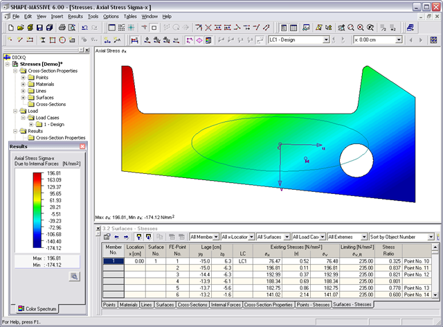
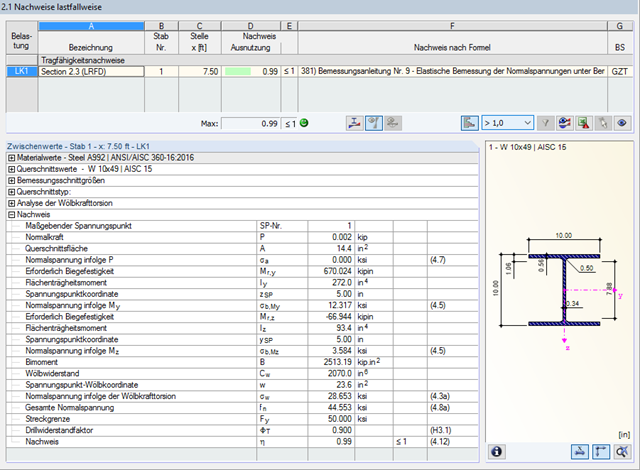
- Normal stresses σx due to axial force and bending
- Shear stresses τ due to shear force and torsion
- Equivalent stresses σv compared to limit stress
- Stress ratios related to equivalent stresses
- Normal stress σx due to unit axial force N
- Shear stress τ due to unit shear forces Vy, Vz, Vu, Vv
- Normal stress σx due to unit momentsMy, Mz, Mu, Mv

Various design parameters of the cross-sections can be adjusted in the serviceability limit state configuration. The applied cross-section condition for the deformation and crack width analysis can be controlled there.
For this, the following settings can be activated:
- Crack state calculated from associated load
- Crack state determined as an envelope from all SLS design situations
- Cracked state of cross-section - independent of load

Do you work with the structural components consisting of slabs? In that case, you have to perform the shear force design with the requirements of punching shear design, for example, according to 6.4, EN 1992‑1‑1. In addition to floor slabs, you can also design foundation slabs in this way.
In the Ultimate Configuration for concrete design, you can define the punching design parameters for the selected nodes.
Snow loads can be generated as member loads on flat/monopitch roofs and duopitch roofs.
Additional snow loads such as drifted snow loads, snow overhangs, and snow guards can be taken into account as well.
The following standards are available:
-
EN 1991-1-3 (incl. National Annexes)
-
DIN 1055-5
-
CTE DB-SE-AE
-
ASCE/SEI 7-16

The new steel sections according to the latest CISC Handbook (12th edition) are available in RFEM 6. The sections are listed in the Standardized library. In the filter, select “Canada” for the region and “CISC 12” for the standard. Alternatively, the section name can be directly entered in the search box located at the bottom of the dialog box.

The design of cold-formed steel members according to the AISI S100-16 / CSA S136-16 is available in RFEM 6. Design can be accessed by selecting “AISC 360” or “CSA S16” as the standard in the Steel Design Add-on. “AISI S100” or “CSA S136” is then automatically selected for the cold-formed design.
RFEM applies the Direct Strength Method (DSM) to calculate the elastic buckling load of the member. The Direct Strength Method offers two types of solutions, numerical (Finite Strip Method) and analytical (Specification). The FSM signature curve and buckling shapes can be viewed under Sections.

The initial stiffness Sj,ini is a crucial parameter for evaluating whether a connection can be characterized as rigid, semi-rigid, or pinned.
In the "Steel Joints" add-on, you can calculate the initial stiffness Sj,ini according to Eurocode (EN 1993‑1‑8, Section 5.2.2) and AISC (AISC 360-16, Cl. E3.4) with regard to the internal forces N, My, and/or Mz.
The optional automatic transfer of initial stiffnesses allows for a directly transfer as member hinge stiffnesses in RFEM. The entire structure is then recalculated and the resulting internal forces are automatically adopted as loads in the analysis and design of the connection models.
This automated iteration process eliminates the need for manual export and import of data, reducing the amount of work and minimizing potential sources of error.
Explanatory Video: Calculation of Initial Stiffness Sj,ini
You can perform the calculation of the warping torsion on the entire system. Thus, you consider the additional 7th degree of freedom in the member calculation. The stiffnesses of the connected structural elements are automatically taken into account. It means, you don't need to define equivalent spring stiffnesses or support conditions for a detached system.
You can then use the internal forces from the calculation with warping torsion in the add-ons for the design. Consider the warping bimoment and the secondary torsional moment, depending on the material and the selected standard. A typical application is the stability analysis according to the second-order theory with imperfections in steel structures.
Did you know that The application is not limited to thin-walled steel cross-sections. Thus, it is possible for you, for example, to perform the calculation of the ideal overturning moment of beams with solid timber cross-sections.
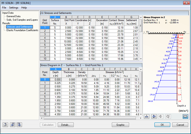
The calculated stresses and settlements are displayed in result windows. In addition, it is possible to evaluate the results graphically. The graphic displays the position and the layer arrangement of the soil samples to clarify the results.
The final result window shows the elastic foundation coefficients. Graphical evaluation is possible as well.
Due to the integrated RF-/STEEL Warping Torsion module extension, it is possible to perform the design according to Design Guide 9 in RF-/STEEL AISC.
The calculation is performed with 7 degrees of freedom according to the warping torsion theory and enables a realistic stability design, including consideration of torsion.

In the Steel Joints add-on, you can design connections according to the American standard ANSI/AISC 360‑16. The following design procedures are integrated:
- Load and Resistance Factor Design (LRFD)
- Allowable Stress Design (ASD)
- Consideration of 7 local deformation directions (ux, uy, uz, φx, φy, φz, ω) or 8 internal forces (N, Vu, Vv, Mt,pri, Mt,sec, Mu, Mv, Mω) when calculating member elements
- Usable in combination with a structural analysis according to linear static, second-order, and large deformation analysis (imperfections can also be taken into account)
- In combination with the Stability Analysis add-on, allows you to determine critical load factors and mode shapes of stability problems such as torsional buckling and lateral-torsional buckling
- Consideration of end plates and transverse stiffeners as warping springs when calculating I-sections with automatic determination and graphical display of the warping spring stiffness
- Graphical display of the cross-section warping of members in the deformation
- Full integration with RFEM and RSTAB
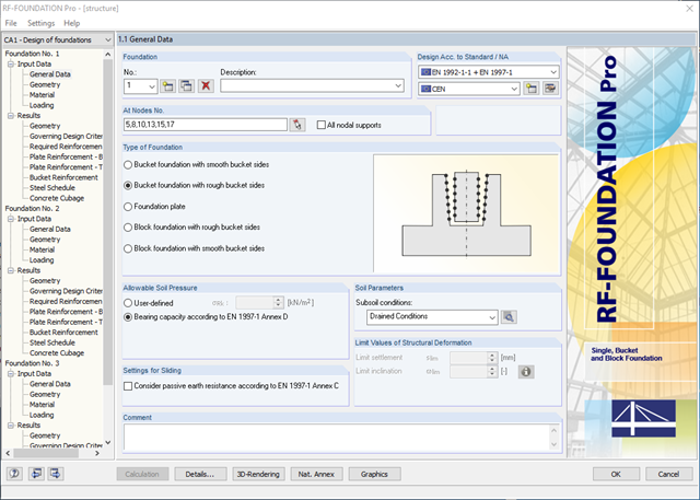
- Available types of foundation:Pure foundation plate (optionally without reinforcement)
- Bucket foundation with smooth bucket sides
- Bucket foundation with rough bucket sides
- Block Foundation with Smooth Bucket Sides
- Block foundation with rough bucket sides
- Design according to EN 1992-1-1 and EN 1997-1
- The following National Annexes of Eurocode 2 and Eurocode 7 are available:
-
DIN EN 1992-1-1/NA/A1:2015-12 | DIN EN 1997-1/NA:2010-12
-
 ÖNORM B 1992-1-1:2018-01 | ÖNORM B 1997-1:2007-11
 -
 DK EN 1992-1-1/NA:2013 | DK EN 1997-1/NA:2007
 -
 BDS EN 1992-1-1:2005/NA:2011 | BDS EN 1997-1:2005/NA:2012
 -
 SFS EN 1992-1-1/NA:2007-10 | SFS EN 1997-1/NA:2004-01
 -
 NF EN 1992-1-1/NA:2016-03 | NF EN 1997-1/NA:2006-09
 -
 UNI EN 1992-1-1/NA:2007-07 | DIN EN 1997-1/NA:2005-01
 -
 NEN EN 1992-1-1 C2:2011/NB:2016-11 | NEN EN 1997-1+C1:2012/NB:2012
 -
 PN EN 1992-1-1/NA:2010 | PN EN 1997-1/NA:2005-05
 -
 STN EN 1992-1-1/NA:2008-06 | STN EN 1997-1/NA:2005-10
 -
 SIST EN 1992-1-1:2005/A101:2006 | SIST EN 1997-1/NA:2006-03
 -
UNE EN 1992-1-1/NA:2013 | UNE EN 1997-1:2010
-
 EN 1992-1-1/NA:2008 | Svensk EN 1997-1:2005/AC:2009
 -
 CSN EN 1992-1-1/NA:2016-05 | CSN EN 1997-1/NA:2014-06
 -
 BS EN 1992-1-1:2004/NA:2005 | BS EN 1997-1:2004
 -
 TKP EN 1992-1-1:2009 | TKP EN 1997-1:2009
 -
 CYS EN 1992-1-1:2004/NA:2009 | CYS EN 1997‑1/NA:2004
-
In addition to the National Annexes (NA) listed above, you can also define a specific NA, applying user‑defined limit values and parameters.
- Automatic calculation of governing loading from load cases
- Specification of additional support forces
- Determination of the reinforcement proposal for the bottom and top plate reinforcement considering the most favorable combination of mat and rebars
- Individual adjustment of reinforcement proposal
- Results of foundation reinforcement in detailed reinforcement drawings
- Results displayed in tables and graphics
- Visualization of foundation, columns, and reinforcement in 3D rendering