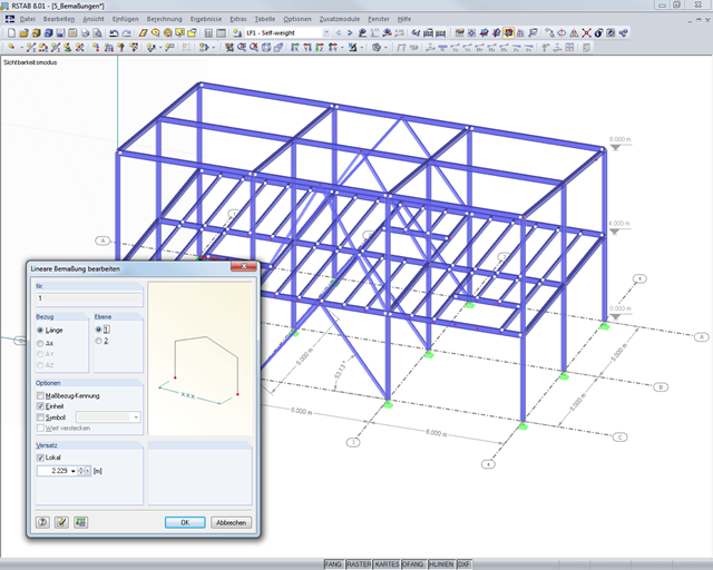
It is possible to selectively display or hide various objects such as nodes, members, supports, and others. The model can be dimensioned by using lines, arcs, inclinations, or height elevations. Freely created guidelines, sections, and comments facilitate the input and evaluation. You can also display or hide the guide objects individually.
Go to Explanatory Video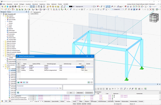
Do you want to efficiently process recurring systems? Then the parameterized input is recommended to you. You can create your models by using particular parameters and adjust them to a new situation by modifying the parameters.
Work more efficiently by freely adjusting the display of your model. You can selectively display or hide various objects, such as nodes, members, supports, and others. Dimension your model by using lines, arcs, inclinations, or height elevations. Freely created guidelines, sections, and comments facilitate you the input and evaluation. You can also display or hide the guide objects individually.
Go to Explanatory VideoWork on your models with efficient and precise calculations in the digital wind tunnel. RWIND 2 uses a numerical CFD model (Computational Fluid Dynamics) to simulate wind flows around objects. Specific wind loads are generated from the simulation process for RFEM or RSTAB.
RWIND 2 performs this simulation using a 3D volume mesh. The program provides automatic meshing; you can easily set the entire mesh density as well as the local mesh refinement on the model using a few parameters. A numerical solver for incompressible turbulent flows is used to calculate the wind flows and the surface pressures on the model. The results are then extrapolated to your model. RWIND 2 is designed to work with different numerical solvers.
We currently recommend using the OpenFOAM® software package, which has provided very good results in our tests and is also a frequently used tool for CFD simulations. Alternative numerical solvers are under development.
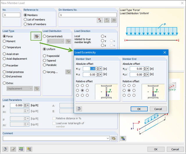
You can define eccentricities for member loads of the load type 'Force'. You can apply the load eccentricities by means of an absolute or relative offset.
We recommend using the large deformation analysis to consider all effects of eccentric loads.
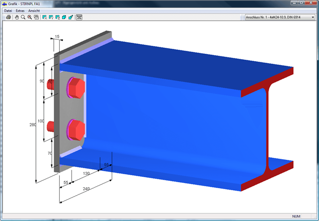
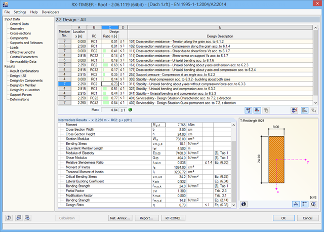
All design results and design checks are displayed in detail and in a comprehensible manner. An error log indicates non-designable situations or failed recommendations. Due to the permanent integration in RFEM/RSTAB, subsequent modifications in the structural system and in loading are automatically taken into account for the connections to be checked.
If one of the designs could not be fulfilled, the corresponding line is highlighted in red. The output appears in a short or a long form in the global printout report of RFEM/RSTAB. Furthermore, you can easily export all result tables to MS Excel or in a CSV file. A special transfer menu defines all specifications required for the export.
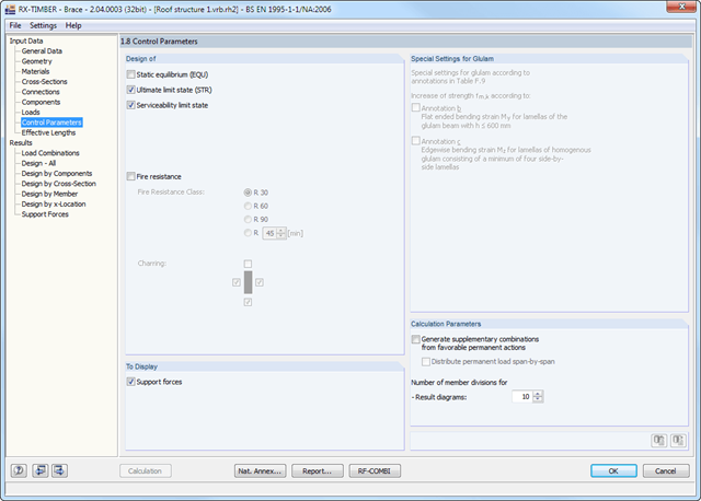
In RX-TIMBER Brace, the following settings for the calculation can be made:*Selection of the designs to be performed
- Determination of displaying support forces and deformations
- Adjustment of recommended limit values for deformation analyses in the ultimate and the serviceability limit state design
- Free definition of parameters for the fire resistance design performed according to the simplified method
- Consideration of material nonlinearities (failing members)
You can define the design type to be performed in the Control Parameters window.
In RX-TIMBER Roof, you can set the following calculation specifications: *Selection of the designs to be performed (ULS, SLS, fire resistance)
- Determination of displaying support forces and deformations
- Adjusting the recommended limit values for the serviceability limit state
- Definition of parameters for fire resistance design according to the simplified method
- Increasing strengths according to EN 1995‑1‑1, Clause 3.2
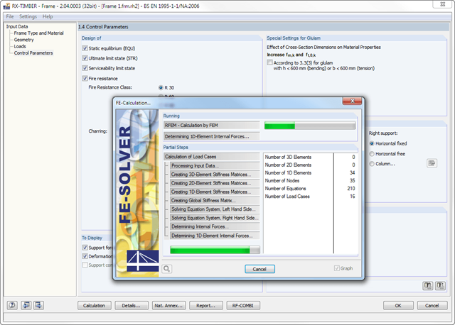
In RX-TIMBER Frame, the following calculation settings are available:
- Design of ULS, SLS, and/or fire resistance Selection of designs to be performed
- Determination of displaying support forces and deformations
- Adjusting the recommended limit values for the deformation analyses
- Free definition of parameters for the fire resistance design performed according to the simplified method
- Increasing bending stiffnesses for flat‑ended bending strains
Separate design cases allow for a flexible analysis of specific actions as well as for individual stability analyses. You can define the design type to be performed in the Control Parameters window.
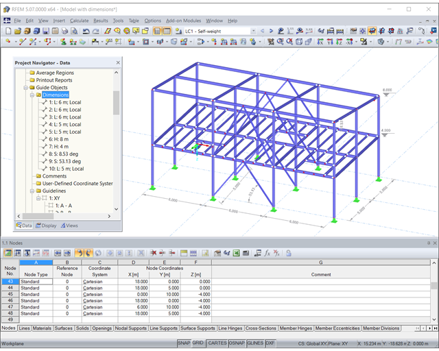
Customize your model to work even more efficiently. You can selectively display or hide various objects, such as nodes, members, supports, and others. The model can be dimensioned by using lines, arcs, inclinations, or height nodes. Freely createable guidelines, sections, and comments facilitate you the input and evaluation. You can also display or hide the guide objects individually.
It is possible to selectively display or hide various objects such as nodes, members, supports, and others. You can dimension the model by using lines, archs, inclinations, or height elevations. Freely created guidelines and comments facilitate the input and evaluation. You can also display or hide the guide objects individually.
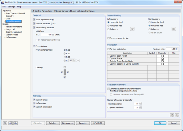
In RX-TIMBER Glued-Laminated Beam, the following calculation settings are available:
- Design of ULS, SLS, and/or fire resistance
- Selection of designs to be performed
- Determination of displaying support forces and deformations
- Adjusting the recommended limit values for the deformation analyses
- Definition of parameters for the fire resistance design performed according to the simplified method (optionally for F 30‑B, F 60‑B, F 90‑B, and user‑defined)
- Determination of tilting moment for pinned support
- Definition of support conditions for a beam
- Beam optimization by means of:
- Beam depth modification
- Modification of beam scene
- cross-section width
- Spacing of lateral supports
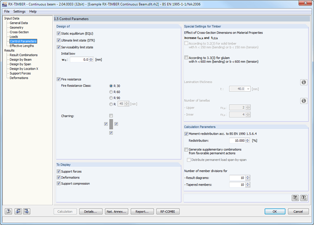
In RX-TIMBER Continuous Beam, the following calculation specifications are available:
- Design of ULS, SLS, and/or fire resistance
- Selection of designs to be performed
- Determination of displaying support forces and deformations
- Adjusting the recommended limit values for the serviceability limit state
- Definition of parameters for fire resistance design according to the simplified method
- Optional vibration design
- Full integration in RFEM/RSTAB with import of relevant internal forces
- Design checks for the elastic-elastic and elastic-plastic methods
- Graphical selection of members and sets of members for design
- Analysis for several load and design cases
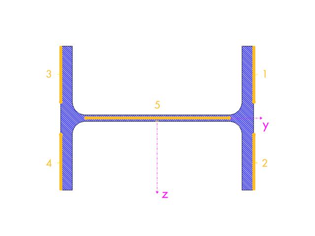
- Design based on the buckling field parameters integrated in the cross-section library for the cross-section parts supported on one and both sides
- Optional determination of shear stresses according to comment on El. (745)
- Possibility to consider the weld thickness in the design of welded cross-sections, which has the effect of a shortening of the cross-section part width
- Cross-section optimization with the option to export modified cross-sections