- Full integration in RFEM/RSTAB with import of relevant internal forces
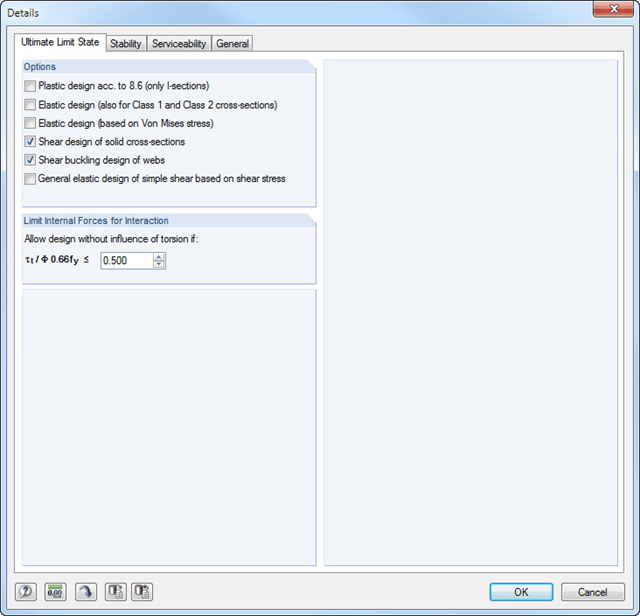
- Design checks for the elastic-elastic and elastic-plastic methods
- Graphical selection of members and sets of members for design
- Analysis for several load and design cases
- Design based on the buckling field parameters integrated in the cross-section library for the cross-section parts supported on one and both sides
- Optional determination of shear stresses according to comment on El. (745)
- Possibility to consider the weld thickness in the design of welded cross-sections, which has the effect of a shortening of the cross-section part width
- Cross-section optimization with the option to export modified cross-sections
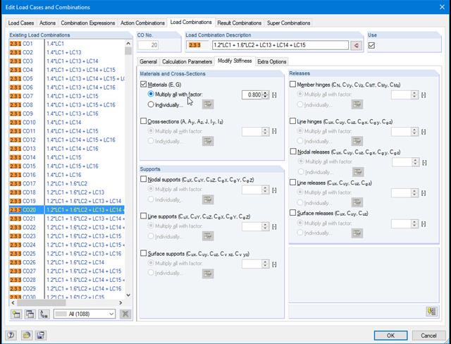
Do not lose track of stiffnesses and initial deformations. In the individual load cases or combinations, you have the option to modify the stiffnesses of materials, cross-sections, nodal, line and surface supports, and member and line hinges for all or selected members. You can also consider initial deformations from other load cases or load combinations.

- Analysis of time diagrams and accelerograms (acceleration-time diagrams exciting the supports of a structure)
- Combination of user-defined time diagrams with nodal, member, and surface loads, as well as free and generated loads
- Combination of several independent excitation functions
- Linear implicit Newmark analysis or modal analysis in time history
- Structural damping using Raleigh damping coefficients or Lehr's damping value
- Graphical display of results in calculation diagrams
- Result display in individual time steps or as an envelope during the entire time period
- Extensive library of seismic events (accelerograms)
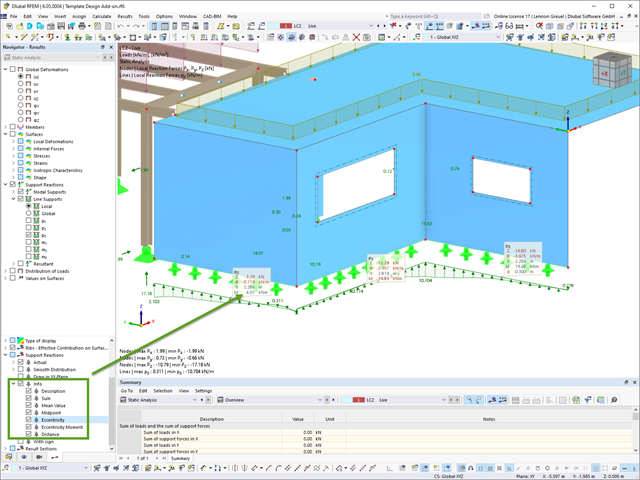
For line support results, you can optionally display certain additional information in info bubbles, such as description, sum, mean value, and so on.
If necessary, you can activate the info bubbles in the Navigator – Results.
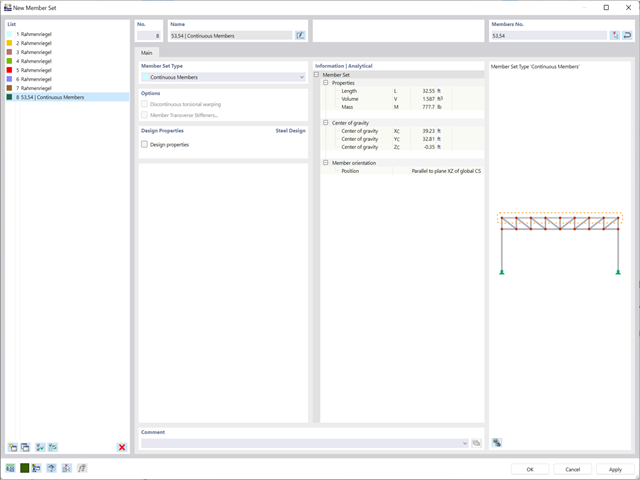
Planning with members is also facilitated in the programs due to specific features. You can arrange members eccentrically, support them by elastic foundations, or define them as rigid links. Member sets allow you to easily apply the load on several members.
In RFEM, you can also define eccentricities of surfaces. Here, you can transform nodal and linear loads into surface loads. If necessary, divide surfaces into surface components and members into surfaces.
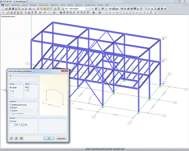
It is possible to selectively display or hide various objects such as nodes, members, supports, and others. The model can be dimensioned by using lines, arcs, inclinations, or height elevations. Freely created guidelines, sections, and comments facilitate the input and evaluation. You can also display or hide the guide objects individually.
Go to Explanatory Video
The program does a lot of work for you. For example, the load or result combinations required for the serviceability limit state are generated and calculated in RFEM/RSTAB. You can select these design situations for the deflection analysis in the Aluminum Design add-on. Depending on the specified precamber and reference system, the program determines the deformation values at each location of a member. They are then compared to the limit values.
You can specify the deformation limit value individually for each structural component in Serviceability Configuration. In this case, you define the maximum deformation depending on the reference length as the allowable limit value. By defining design supports, you can segment the components. In this way, you can determine the corresponding reference length automatically for each design direction.
And that's not all. Based on the position of the assigned design supports, the program allows you to automatically determine the distinction between beams and cantilevers. The limit value is thus determined accordingly.
When calculating the deflection limit, you have to consider certain reference lengths. You can define these reference lengths and the segments to be checked independently of each other, depending on the direction. For this, define design supports at the intermediate nodes of a member and assign them to the respective direction for the deformation analysis. Thus, the segments are created where you can define a precamber for each direction and segment.
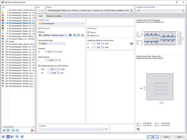
RFEM supports you and save you a lot of work. The materials and surface thicknesses defined in RFEM are already preset in the Concrete Design add-on. Thus, you can directly define the nodes to be designed.
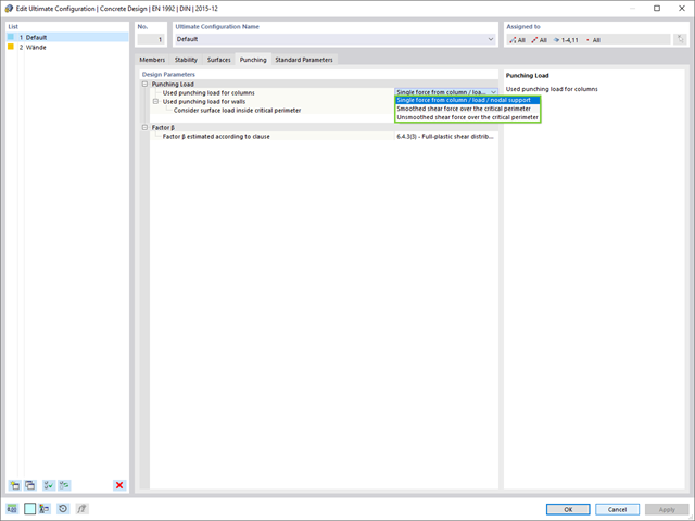
Any openings in the area with risk of punching shear are automatically taken into account in the RFEM model. The add-on recognizes the position of the nodes of punching shear and automatically determines whether it is a node of punching shear in the center of the slab, on the edge of the slab, or in a slab corner. Again, you save your time.
You can individually select the method for determining the load increment factor β.
- Design of tension, compression, bending, shear, and combined internal forces
- Stability analysis for flexural buckling and lateral-torsional buckling
- Automatic determination of critical buckling loads and critical buckling moments for general load applications and support conditions by means of a special FEA program (eigenvalue analysis) integrated in the module
- Optional application of discrete lateral supports to beams
- Automatic cross-section classification
- Deformation analysis (serviceability)
- Cross-section optimization
- Wide range of cross-sections available, such as rolled I-sections, C-sections, rectangular hollow sections, angles, double angles (arrangement flange on flange), T-sections. Welded sections: I-shaped (symmetrical and asymmetrical about major axis), channel sections (symmetrical about major axis), rectangular hollow sections (symmetrical and asymmetrical about major axis), angles, round pipes, and round bars
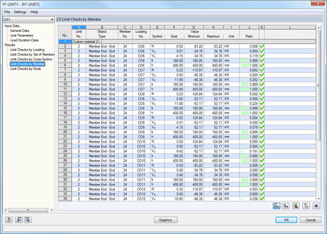
- Clearly arranged result tables
- Detailed result documentation including references to design equations of the used standard
- Various filter and sorting options of results, including result lists by member, cross-sections, x-location, or by load case, load and result combination
- Result table of member slenderness and governing internal forces
- Parts list with weight and solid specifications
- Seamless integration in RFEM/RSTAB

- Automatic consideration of masses from self-weight
- Direct import of masses from load cases or load combinations
- Optional definition of additional masses (nodal, linear, or surface masses, as well as inertia masses) directly in the load cases
- Optional neglect of masses (for example, mass of foundations)
- Combination of masses in different load cases and load combinations
- Preset combination coefficients for various standards (EC 8, SIA 261, ASCE 7,...)
- Optional import of initial states (for example, to consider prestress and imperfection)
- Structure Modification
- Consideration of failed supports or members/surfaces/solids
- Definition of several modal analyses (for example, to analyze different masses or stiffness modifications)
- Selection of mass matrix type (diagonal matrix, consistent matrix, unit matrix), including user-defined specification of translational and rotational degrees of freedom
- Methods for determining the number of mode shapes (user-defined, automatic - to reach effective modal mass factors, automatic - to reach the maximum natural frequency - only available in RSTAB)
- Determination of mode shapes and masses in nodes or FE mesh points
- Results of eigenvalue, angular frequency, natural frequency, and period
- Output of modal masses, effective modal masses, modal mass factors, and participation factors
- Masses in mesh points displayed in tables and graphics
- Visualization and animation of mode shapes
- Various scaling options for mode shapes
- Documentation of numerical and graphical results in printout report

Have you created the entire structure in RFEM? Very well, now you can assign the individual structural components and load cases to the corresponding construction stages. In each construction stage, you can modify release definitions of members and supports, for example.
You can thus model structural modifications, such as those that occur when bridge girders are successively grouted or when columns are settled. Then, assign the load cases created in RFEM to the construction stages as permanent or non-permanent loads.
Did you know that The combinatorics allows you to superimpose the permanent and non-permanent loads in load combinations. In this way, it is possible for you to determine the maximum internal forces of different crane positions or to consider temporary mounting loads available in one construction stage only.

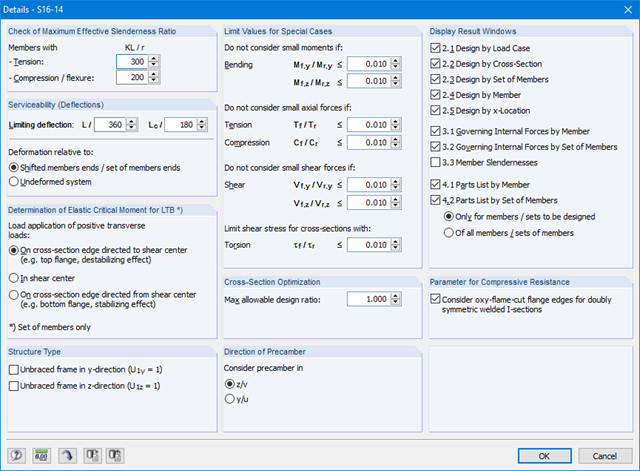
Note that the definition of the effective lengths in the Aluminum Design add-on is an essential requirement for the stability analysis. For this, define the nodal supports and effective length factors in the input dialog box. Do you want to clearly document the nodal supports and the resulting segments with the associated effective length factors? To check the input data, it is best for you to use the graphic display in the RFEM/RSTAB work window. Thus, you can comprehend the design at any time with minimum effort.
- Simple definition of construction stages in the RFEM structure including visualization
- Adding, removing, modifying, and reactivating member, surface, and solid elements and their properties (for example, member and line hinges, degrees of freedom for supports, and so on)
- Automatic and manual combinatorics with load combinations in the individual construction stages (for example, to consider mounting loads, mounting cranes, and other loads)
- Consideration of nonlinear effects such as tension member failure or nonlinear supports
- Interaction with other add-ons, such as Nonlinear Material Behavior, Structure Stability, Form-Firnding, and so on.
- Display of results numerically and graphically for individual construction stages
- Detailed printout report with documentation of all structural and load data for each construction stage
First, the governing design checks of the connection for the respective load case, and load combination, or result combination are displayed. In addition, it is possible to display results separately for sets of members, surfaces, cross-section, members, nodes, and nodal supports.
- You can use a filter to further reduce the displayed results and thus present them in a clearer way.

Your RFEM/RSTAB program is responsible for generating and calculating the load and result combinations required for the serviceability limit state. Select the design situations for the deflection analysis in the Timber Design add-on. The calculated deformation values are then determined at each location of a member, depending on the specified precamber and the reference system, and then compared to the limit values.
You can specify the deformation limit value individually for each structural component in Serviceability Configuration. In this case, the maximum deformation should not exceed the permissible limit value, depending on the reference length. When defining design supports, you can segment the components. This allows you to determine the corresponding reference length automatically for each design direction.
Based on the position of the assigned design supports, the program automatically determines the difference between beams and cantilevers. Thus, you can be sure that the limit value is determined accordingly.
- Design of members and sets of members for tension, compression, bending, shear, combined internal forces, and torsion
- Stability analysis of buckling, torsional, and flexural-torsional buckling
- Automatic determination of critical buckling loads and critical buckling moments for general load applications and support conditions by means of a special FEA program (eigenvalue analysis) integrated in the module
- Alternative analytical calculation of the critical buckling moment for standard situations
- Optional application of discrete lateral supports to beams and continuous members
- Automatic cross-section classification
- Serviceability limit state design (deflection)
- Cross-section optimization
- A wide range of available cross-sections, such as rolled I-sections; channel sections; T-sections; angles; rectangular and circular hollow sections; round bars; symmetrical and asymmetrical, parametric I-, T-, and angle sections; double angles
- Clearly arranged input and result windows
- Detailed result documentation including references to design equations of the used standard
- Various filter and sorting options of results, including result lists by member, cross-sections, x-location, or by load case, load and result combination
- Result tables of member slenderness and governing internal forces
- Parts list with weight and solid specifications
- Seamless integration in RFEM/RSTAB
- Units metric and imperial
Dlubal Software makes many of your work steps easier to support you. Thus, the surfaces, members, member sets, materials, surface thicknesses, and sections defined in RFEM/RSTAB are preset to facilitate the data input. You can use the [Select] function at many places of the program to select the elements graphically. Furthermore, you have an access to the global material and cross-section libraries.
You can group surfaces or members into "Configurations", each with different design parameters. This way, it is possible for you to efficiently calculate design alternatives with different boundary conditions or modified cross-sections, for example. You will be amazed how much faster everything works with RFEM/RSTAB.

Compared to the RF‑/STAGES add-on module (RFEM 5), the following new features have been added to the Construction Stages Analysis (CSA) add-on for RFEM 6:
- Consideration of construction stages at RFEM level
- Integration of the construction stage analysis into the combinatorics in RFEM
- Additional structural elements, such as line hinges, are supported
- Analysis of alternative construction processes in a model
- Reactivation of elements
- Design of members and sets of members for tension, compression, bending, shear, torsion, and combined internal forces
- Stability analysis of buckling, torsional, and flexural-torsional buckling
- Automatic determination of critical buckling loads and critical buckling moments for general load applications and support conditions by means of a special FEA program (eigenvalue analysis) integrated in the module
- Alternative analytical calculation of the critical buckling moment for standard situations
- Optional application of discrete lateral supports to beams and continuous members
- Automatic cross-section classification
- Serviceability limit state design (deflection)
- Cross-section optimization
- A wide range of available cross-sections, such as rolled I-sections; channel sections; T-sections; angles; rectangular and circular hollow sections; round bars; symmetrical and asymmetrical, parametric I-, T-, and angle sections; double angles
- Clearly arranged input and result windows
- Detailed result documentation including references to design equations of the used standard
- Various filter and sorting options of results, including result lists by member, cross-sections, x-location, or by load case, load and result combination
- Result tables of member slenderness and governing internal forces
- Parts list with weight and solid specifications
- Seamless integration in RFEM/RSTAB