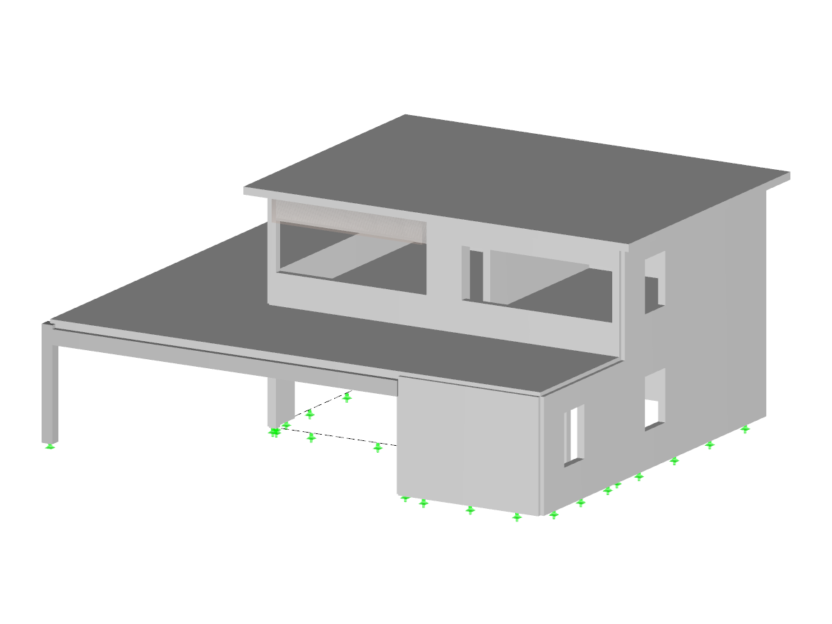
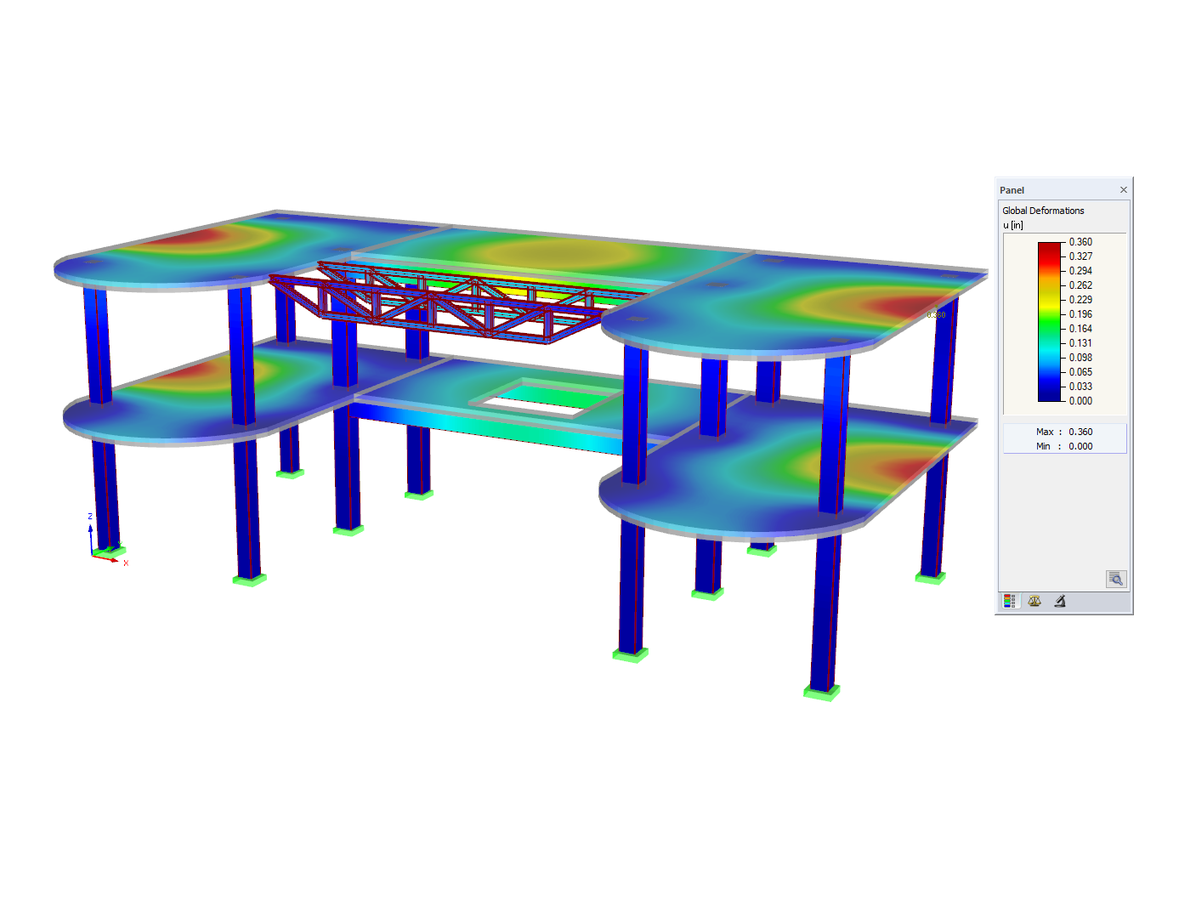
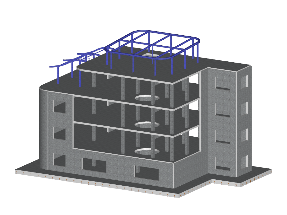
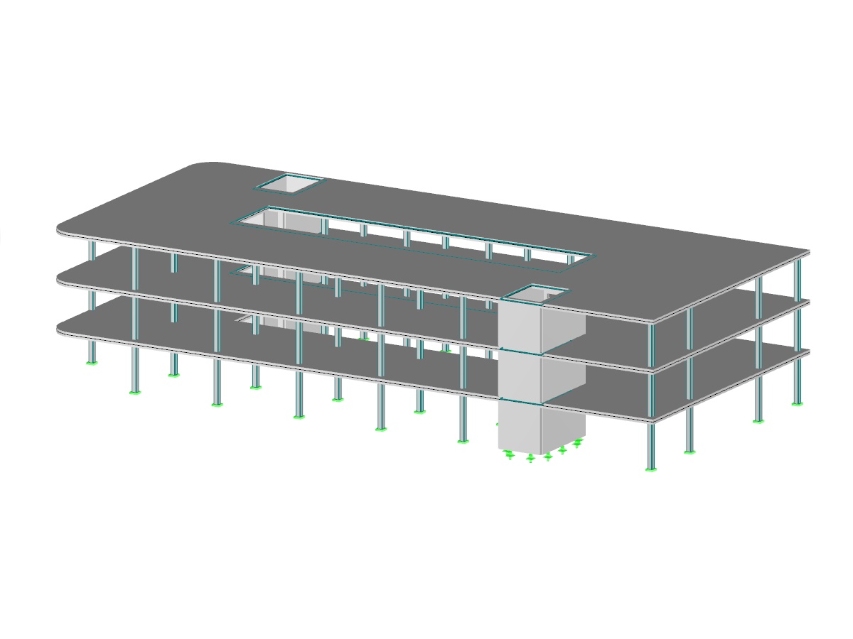
Concrete member and surface structure modeled in RFEM. The webinar in the link below demonstrates the design workflow according to the CSA A23.3:19 standard utilizing the RF-CONCRETE Members and Surfaces add-on modules.
- Webinar # 1 - Introduction to RFEM based on FEM
- RFEM 6 | Dynamic Analysis and Seismic Design According to EC 8
- RSECTION | Students | Introduction to Strength of Materials
- CSA A23.3:19 Concrete Design in RFEM
- RFEM | Basics
- RFEM | Basics
- RFEM | Basics
- RFEM | Structural Dynamics and Seismic Design
- ACI 318-19 Concrete Design in RFEM
- RFEM | Structural Dynamics and Seismic Design
- RFEM | Structural Dynamics and Seismic Design According to EC 8
- RFEM | Basics
- RFEM | Dynamic analysis and anti-seismic design according to EC 8
- RFEM | Structural dynamics and earthquake design according to EC 8
- RFEM | Structural Dynamics and Seismic Design According to EC 8
- RFEM | Structural dynamics and earthquake design according to EC 8
- RFEM | Structural Dynamics and Seismic Design According to EC 8
- RFEM | Basics
- RFEM | Basics
- Eurocode 8 | Structural Dynamics and Seismic Design
- RFEM | Dynamics | USA
- RFEM | Structural Dynamics and Seismic Analysis According to EC 8
- Online Introductory Training RFEM - KTH Royal Institute of Technology
- RFEM | Dynamic Analysis and Seismic Design According to EC 8
- RFEM | Structural Dynamics and Seismic Analysis According to EC 8
- RFEM 5 | Basics
- RFEM | Structural Dynamics and Seismic Design According to EC 8
- RFEM 5 | Structural Dynamics and Seismic Design According to EC 8
- RFEM 6 | Basics
- RFEM 6 | Structural Dynamics and Seismic Design According to EC 8
- RFEM 6 | Dynamic Analysis and Seismic Design According to EC 8
- RFEM 6 | Basics
- RFEM 6 | Basics
- RFEM 6 | Structural Dynamics and Seismic Design According to EC 8
- RFEM 6 | Dynamic Analysis and Seismic Design According to EC 8
- RFEM 6 | Basics
- RFEM 6 | Structural Dynamics and Seismic Design According to EC 8
- RFEM 6 | Dynamic Analysis and Seismic Design According to EC 8
- RSECTION | Students | Introduction to Strength of Materials
- RFEM | Basics | HTW Saar
- RFEM 6 | Basics
- RFEM 6 | Basics
- RFEM 6 | Structural Dynamics and Seismic Design According to EC 8
- RFEM 6 | Dynamic Analysis and Seismic Design According to EC 8
- RFEM 6 | Basics | Deggendorf Institute of Technology
- RSECTION | Students | Introduction to Strength of Materials
- RFEM 6 | Dynamic Analysis and Seismic Design According to EC 8
- RSECTION | For Students | Introduction to Strength of Materials
- RFEM 6 | Dynamic Analysis and Seismic Design According to EC 8
- RFEM 6 for Students | Introduction to Strength of Materials | Apr 26, 2023
- RFEM 6 for Students | Introduction to Strength of Materials
CSA A23.3:19 Concrete Structure
Number of Nodes | 125 |
Number of Lines | 144 |
Number of Members | 33 |
Number of Surfaces | 23 |
Number of Solids | 0 |
Number of Load Cases | 4 |
Number of Load Combinations | 14 |
Number of Result Combinations | 2 |
Total Weight | 901.247 tons |
Dimensions | 110 x 48 x 40 feet |
You can download this structural model to use it for training purposes or for your projects. However, we do not assume any guarantee or liability for the accuracy or completeness of the model.
The material library already includes the Canadian types of concrete and reinforcing steel available for design. However, you can always define other materials for the design according to CSA A23.3.
The units used for the reinforced concrete design according to CSA A23.3 are adjusted to the metric system by default.
After the calculation, the module shows clearly arranged tables listing the deformation analysis results. All intermediate values are displayed in a comprehensible manner. Graphical representation of design ratios and deformation in RFEM allows a quick overview of critical areas.
Since the design results are displayed by surface or by point including all intermediate results, you can retrace all details of the calculation. The complete integration of results in the RFEM printout report guarantees verifiable structural design.
Do you have individual column sections and angled wall geometries, and need punching shear design for them?
No problem. In RFEM 6, you can perform punching shear design not only for rectangular and circular sections, but for any cross-section shape.
The building model is calculated in two phases:
- Global 3D calculation of the global model, where the slabs are modeled as a rigid plane (diaphragm) or as a bending plate
- Local 2D calculation of the individual floors
After the calculation, the results of the columns and walls from the 3D calculation and the results of the slabs from the 2D calculation are combined in a single model. This means that there is no need to switch between the 3D model and the individual 2D models of the slabs. The user only works with one model, saves valuable time, and avoids possible errors in the manual data exchange between the 3D model and the individual 2D ceiling models.
The vertical surfaces in the model can be divided into shear walls and opening lintels. The program automatically generates internal result members from these wall objects, so they can be designed as members according to any standard in the Concrete Design add-on.