- Full integration in RFEM/RSTAB with import of relevant internal forces
- Design checks for the elastic-elastic and elastic-plastic methods
- Graphical selection of members and sets of members for design
- Analysis for several load and design cases
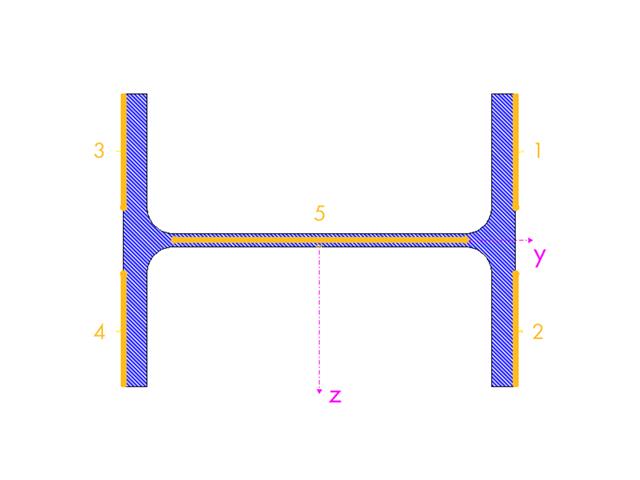
- Design based on the buckling field parameters integrated in the cross-section library for the cross-section parts supported on one and both sides
- Optional determination of shear stresses according to comment on El. (745)
- Possibility to consider the weld thickness in the design of welded cross-sections, which has the effect of a shortening of the cross-section part width
- Cross-section optimization with the option to export modified cross-sections

In RFEM and RSTAB, you can visualize the flow field quantities of pressure, velocity, turbulence kinetic energy, and turbulence dissipation rate for the wind simulation.
The clipping planes are aligned with the respective wind direction.
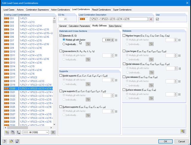
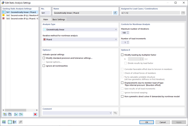
Do not lose track of stiffnesses and initial deformations. In the individual load cases or combinations, you have the option to modify the stiffnesses of materials, cross-sections, nodal, line and surface supports, and member and line hinges for all or selected members. You can also consider initial deformations from other load cases or load combinations.
- Automatic import of internal forces from RFEM/RSTAB
- Optional consideration of creep
- Automatic determination of planned and unintentional eccentricity from the second-order analysis in addition to the existing eccentricity
- Determination of internal forces according to the linear static analysis and the second-order analysis
- Analysis of governing design locations along the column due to existing loading
- Output of the required longitudinal and stirrup reinforcement
- Summary of design ratios, including all design details

- Import of relevant information and results from RFEM
- Integrated, editable material and section library
- Sensible and complete presetting of input parameters
- Punching design on columns (all section shapes), wall ends, and wall corners
- Automatic recognition of the punching node position from an RFEM model
- Detection of curves or splines as a boundary of the control perimeter
- Automatic consideration of all slab openings defined in the RFEM model
- Construction and graphical display of the control perimeter
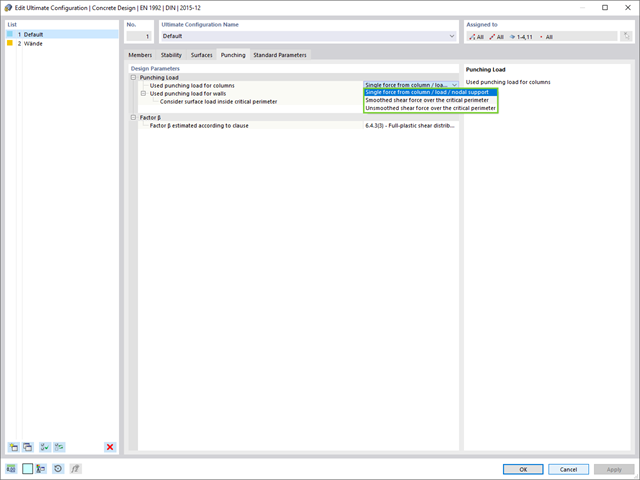
- Optional design with unsmoothed shear stress along the control perimeter that corresponds to the actual shear stress distribution in the FE model
- Determination of the load increment factor β via full-plastic shear distribution as constant factors according to EN 1992‑1‑1, Sect. 6.4.3 (3), based on EN 1992‑1‑1, Fig. 6.21N, or by a user‑defined specification
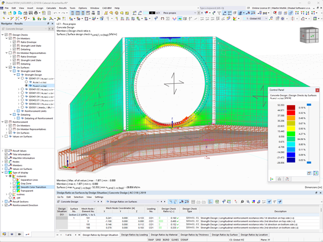
- Numerical and graphical display of results (3D, 2D, and in sections)
- Punching design of the slab without punching reinforcement
- Qualitative determination of the required punching reinforcement
- Design and analysis of the longitudinal reinforcement
- Complete integration of results in an RFEM printout report
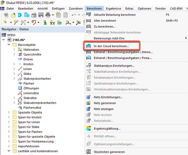
- Outsource calculation on a computing server in the cloud
- Option to select different powerful computing servers
- Clearly arranged display of all calculation tasks in the Extranet
- Calculated files are available for download for two months
- Virtually unlimited computing capacity using cloud technology
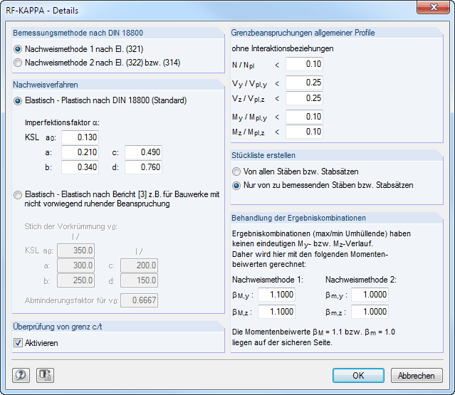
In a separate dialog box, you can specify extensive detailed settings for the design:
Design Method According to DIN 18800
- Design Method 1 According to El. (321)
- Design Method 2 According to El. (322)
Analysis method
- Elastic-Plastic according to DIN 18800
- Elastic-elastic according to a publication by Kretschmar, J./Österrieder, P./beirow, B.
Limit loading of general sections
- General sections – these include all cross-sections that cannot be assigned to single or double symmetric I-sections, box sections, or pipe sections – can also be designed according to the equivalent member method against flexural buckling. In this case, however, the plastic cross-section properties are determined without interaction conditions. The allowable application limits for this consideration depend on the ratio of the existing internal force to the fully plastic internal force. Five text boxes provide the option for user-defined control.
Check of limit (c/t)
- In this dialog section, you can activate or deactivate the check of c/t ratios.
Treatment of Result Combinations
- When designing a result combination, a result set is obtained due to the result superposition on each member location, which makes it impossible to clearly determine the moment factors. In this section, you can thus freely specify a global moment factor for a result combination design. The predefined values are on the safe side, regardless of the design method.
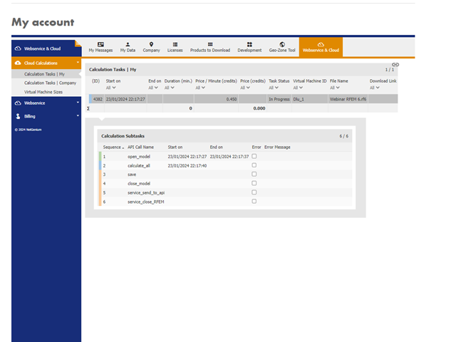
After completing the calculation, you will receive an email with a link to download the calculated file. Large files are compressed into a ZIP archive. Smaller files can be downloaded directly.
As an alternative, there is a link to the calculated file in the Extranet.
The downloaded file is a common RFEM file and can be used for further processing as usual.

- Analysis of time diagrams and accelerograms (acceleration-time diagrams exciting the supports of a structure)
- Combination of user-defined time diagrams with nodal, member, and surface loads, as well as free and generated loads
- Combination of several independent excitation functions
- Linear implicit Newmark analysis or modal analysis in time history
- Structural damping using Raleigh damping coefficients or Lehr's damping value
- Graphical display of results in calculation diagrams
- Result display in individual time steps or as an envelope during the entire time period
- Extensive library of seismic events (accelerograms)
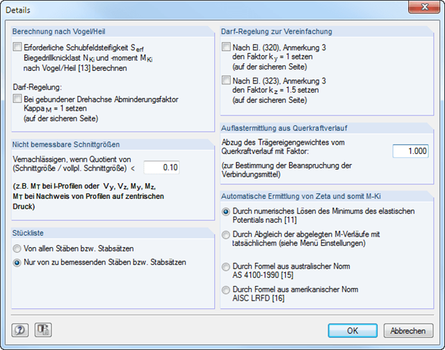
In RF‑/LTB, the design is usually performed according to the equivalent member method according to DIN 18800, Part 2. However, you can specify extensive detailed settings for the design in a separate dialog box:
Design according to Bird/Heil
Optionally, it is possible to apply the method according to Bird/Heil in the program
- the required shear stiffness Sreq
- the lateral-torsional buckling load Nki
- the critical buckling moment Mki
.
This plastic-plastic calculation method is only valid for lateral and torsional restraints with simple bending with simultaneous load introduction on the upper flange. Further requirements that must be met can be found in the program manual. In case of invalid conditions (for example, biaxial bending), RF-/LTB displays the corresponding error message. In addition, the reduction factorκM for the bending moments My can be set to 1.0 if a restrained rotation axis is present.
Non-Designable Internal Forces
It is possible to neglect non-designable internal forces and thus exclude them from the design if the quotient of the internal force and the fully plastic internal force falls below a certain value. This way, you can neglect, for example, a small moment about the minor axis, thus avoiding the method for biaxial bending.
Allowance according to DIN 18800, Part 2, Element (320) and Element (323)
Automatic determination of ζ
If you want the factor for the determination of the ideal elastic critical moment Mcr to be determined automatically, you can select one of the following types:
- Solving the elastic potential numerically
- Comparison of moment diagrams
- Australian Standard AS 4100-1990
- US standard AISC LRFD
When aligning the moment distributions, you can use the library which contains more than 600 moment distributions in tables.

It is necessary to enter the required force-time diagrams. They can be combined in load cases or load combinations of the type Time History Analysis | Time Diagrams with the loading in order to define where and in which direction the force-time diagrams act.
The second option is to enter acceleration-time diagrams, which can be used in the load cases of the Time History Analysis | Accelerogram type.
All calculation parameters are specified in the time history analysis settings. These include, for example, the type of analysis method and the maximum calculation time.

If you have experimentally determined surface pressures available for a model, you can apply them to a structural model in RFEM 6, process them in RWIND 2, and use them as wind loads in the structural analysis of RFEM 6.
You can find out how to apply the experimentally determined values in this technical article.
All design results and design checks are displayed in detail and in a comprehensible manner. An error log indicates non-designable situations or failed recommendations. Due to the permanent integration in RFEM/RSTAB, subsequent modifications in the structural system and in loading are automatically taken into account for the connections to be checked.
If one of the designs could not be fulfilled, the corresponding line is highlighted in red. The output appears in a short or a long form in the global printout report of RFEM/RSTAB. Furthermore, you can easily export all result tables to MS Excel or in a CSV file. A special transfer menu defines all specifications required for the export.

The combination wizard provides you with the option to consider more than one initial state. RFEM and RSTAB allow you to specify different initial states (prestress, form-finding, strain, and so on) for the target combinations in the combinatorics.
You can thus, for example, generate load states on the basis of a form-finding analysis with varying imperfections.
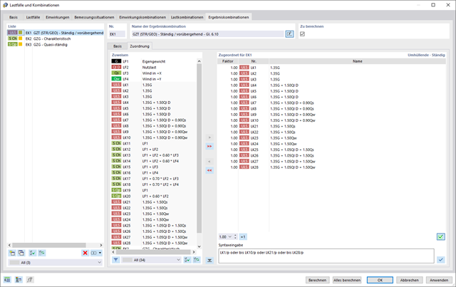
Rely on RFEM 6 even in the case of result combinations. First, you can have the contained load cases calculated in the result combinations. Then, the results are superimposed by taking into account the corresponding factors. In the result combinations, you can superimpose the results of load cases, load combinations, and other result combinations. Internal forces are added together by default. However, you have the option of a square addition, which is relevant for dynamic analysis.
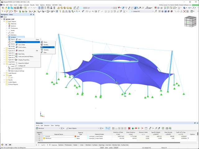
A great strength of the Dlubal programs is their intuitive, easy-to-learn operation. RFEM 6 is no exception. Create your structure in a user interface usual for CAD or via tables. By right-clicking the graphical or navigator objects, a shortcut menu appears, which facilitates you creating or editing the objects. Due to the intuitive user interface, you can create structural and loading objects in a very short time.
Go to Explanatory Video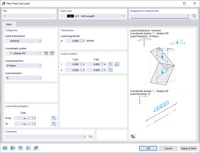
Also for pure member models, such as girder grillages, there is a useful feature for you. Here you can define free line loads (for example, from conveyor belts) and transfer them proportionally to members.

- For the design according to Eurocode 3, the parameters of the National Annexes (NA) are integrated for the following countries:
-
 DIN EN 1993-1-1/NA:2016-04 (Germany)
 -
 ÖNORM EN 1993-1-1/NA:2015-12 (Austria)
 -
 SN EN 1993-1-1/NA:2016-07 (Switzerland)
 -
 BDS EN 1993-1-1/NA:2015-10 (Bulgaria)
 -
 BS EN 1993-1-1/NA:2016-07 (United Kingdom)
 -
 CEN EN 1993-1-1/2015-06 (European Union)
 -
 CYS EN 1993-1-1/NA:2015-07 (Cyprus)
 -
 CZE EN 1993-1-1/NA:2016-06 (Czech Republic)
 -
 DS EN 1993-1-1/NA:2015-07 (Denmark)
 -
 ELOT EN 1993-1-1/NA:2017-01 (Greece)
 -
 EVS EN 1993-1-1/NA:2015-08 (Estonia)
 -
 HRN EN 1993-1-1/NA:2016-03 (Croatia)
 -
 I S. EN 1993-1-1/NA:2016-03 (Ireland)
 -
 ILNAS EN 1993-1-1/NA:2015-06 (Luxembourg)
 -
 IST EN 1993-1-1/NA:2015-11 (Iceland)
 -
 LST EN 1993-1-1/NA:2017-01 (Lithuania)
 -
 LVS EN 1993-1-1/NA:2015-10 (Latvia)
 -
 MS EN 1993-1-1/NA:2010-01 (Malaysia)
 -
 MSZ EN 1993-1-1/NA:2015-11 (Hungary)
 -
 NBN EN 1993-1-1/NA:2015-07 (Belgium)
 -
 NEN EN 1993-1-1/NA:2016-12 (Netherlands)
 -
 NF EN 1993-1-1/NA:2016-02 (France)
 -
 NP EN 1993-1-1/NA:2009-03 (Portugal)
 -
 NS EN 1993-1-1/NA:2015-09 (Norway)
 -
 PN EN 1993-1-1/NA:2015-08 (Poland)
 -
 SFS EN 1993-1-1/NA:2015-08 (Finland)
 -
 SIST EN 1993-1-1/NA:2016-09 (Slovenia)
 -
 SR EN 1993-1-1/NA:2016-04 (Romania)
 -
 SS EN 1993-1-1/NA:2019-05 (Singapore)
 -
 SS EN 1993-1-1/NA:2015-06 (Sweden)
 -
 STN EN 1993-1-1/NA:2015-10 (Slovakia)
 -
 TKP EN 1993-1-1/NA:2015-04 (Belarus)
 -
 UNE EN 1993-1-1/NA:2016-02 (Spain)
 -
 UNI EN 1993-1-1/NA:2015-08 (Italy)
-
- The design according to US standard AISC 360 includes analysis methods according to:
-
 Load and Resistance Factor Design (LRFD)
 -
Allowable Stress Design (ASD)
-

Do you know about RSECTION 1 yet? The stand-alone program RSECTION helps you to determine the section properties for any thin-walled and massive cross-sections. Then, it performs a stress analysis. RSECTION combines the programs SHAPE‑THIN and SHAPE‑MASSIVE. Compared to these programs, we have added the following new features in RSECTION:
- Graphical display of stress components
- Scripting using Javascript
Find out more here:
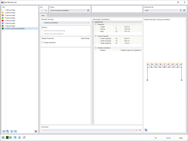
Planning with members is also facilitated in the programs due to specific features. You can arrange members eccentrically, support them by elastic foundations, or define them as rigid links. Member sets allow you to easily apply the load on several members.
In RFEM, you can also define eccentricities of surfaces. Here, you can transform nodal and linear loads into surface loads. If necessary, divide surfaces into surface components and members into surfaces.
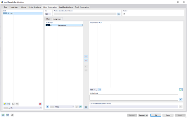
Do you want to combine actions? Then use this feature. Here, the actions are automatically superimposed in accordance with combination expressions and then displayed as "action combinations". You can define which action combinations will eventually be used for the generation of load or result combinations. Based on the created action combinations, you can estimate how the combination expressions affect the number of combinations.
This feature helps you with the load application. You can have the required loading applied incrementally. This option is particularly suitable for your calculations according to the large deformation analysis. Furthermore, you can easily perform post‑critical analyses in RFEM.

The program does a lot of work for you. For example, the load or result combinations required for the serviceability limit state are generated and calculated in RFEM/RSTAB. You can select these design situations for the deflection analysis in the Aluminum Design add-on. Depending on the specified precamber and reference system, the program determines the deformation values at each location of a member. They are then compared to the limit values.
You can specify the deformation limit value individually for each structural component in Serviceability Configuration. In this case, you define the maximum deformation depending on the reference length as the allowable limit value. By defining design supports, you can segment the components. In this way, you can determine the corresponding reference length automatically for each design direction.
And that's not all. Based on the position of the assigned design supports, the program allows you to automatically determine the distinction between beams and cantilevers. The limit value is thus determined accordingly.
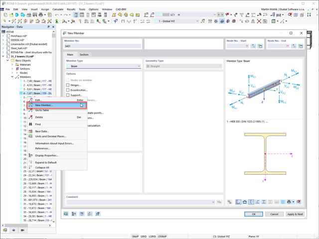
You create your models in the graphical user interface typical for CAD programs. By right-clicking the graphical or navigator objects, you activate a shortcut menu that you can use to select and modify the objects.
The operation of the user interface is intuitive, as you will notice soon. Therefore, you can create the structural and loading objects in a minimum amount of time.
Go to Explanatory Video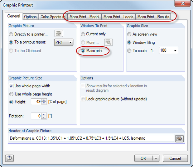
You can print a model, loads, and results using a mass print function. You can create graphics from different defined directions. For example, you can print all internal forces as an isometric view with a single mouse click.

For each load case, the deformations can be displayed at the end time.
These results are also documented for you in the printout report of RFEM and RSTAB. You can select the report contents and extent specifically for the individual design checks.
_(1).png?mw=640&hash=415f7bbaf70e41679bb0106e1cf91eaa8c493ec9)
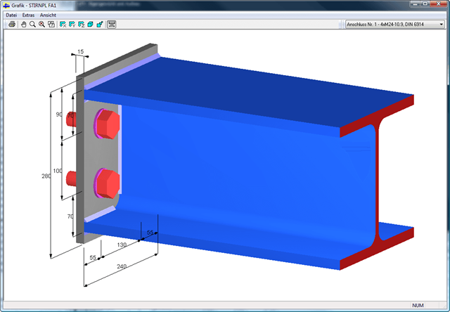
- Automatic generation of FE analysis models: The add-on automatically creates a finite element model (FE) of the steel connection in the background.
- Consideration of all internal forces: The calculation and design checks include all internal forces (N, Vy, Vz, My, Mz, MT) and are not limited to planar loading.
- Automatic load transfer: All load combinations are automatically transferred to the FE analysis model of the connection. The loads are transferred directly from RFEM, so manual data input is not necessary.
- Efficient modeling: The add-on saves you time when modeling complex connection situations. You can also save the created FE analysis model and use it further for your own detailed analyses.
- Extensible library: An extensive and extensible library with predefined steel connection templates is available.
- Wide applicability: The add-on is suitable for connections of any type and shape, compatible with almost all rolled, welded, built-up, and thin-walled cross-sections.

The pushover analysis is managed by a newly introduced analysis type in the load combinations. Here, you have access to the selection of the horizontal load distribution and direction, the selection of a constant load, the selection of the desired response spectrum for the determination of the target displacement, and the pushover analysis settings tailored to the pushover analysis.
In the pushover analysis settings, you can modify the increment of the increasing horizontal load and specify the stopping condition for the analysis. Furthermore, it is possible to easily adjust the precision for the iterative determination of the target displacement.

You have several options available to define masses for a modal analysis. While the masses due to self-weight are considered automatically, you can consider the loads and masses directly in a load case of the modal analysis type. Do you need more options? Select whether to consider full loads as masses, load components in the global Z-direction, or only the load components in the direction of gravity.
The program offers you an additional or alternative option for importing masses: A manual definition of load combinations as of which are the masses considered in the modal analysis. Have you selected a design standard? You can then create a design situation with the Seismic Mass combination type. Thus, the program automatically calculates a mass situation for the modal analysis according to the preferred design standard. In other words: The program creates a load combination on the basis of the preset combination coefficients for the selected standard. This contains the masses used for the modal analysis.
RFEM supports you and save you a lot of work. The materials and surface thicknesses defined in RFEM are already preset in the Concrete Design add-on. Thus, you can directly define the nodes to be designed.
Any openings in the area with risk of punching shear are automatically taken into account in the RFEM model. The add-on recognizes the position of the nodes of punching shear and automatically determines whether it is a node of punching shear in the center of the slab, on the edge of the slab, or in a slab corner. Again, you save your time.
You can individually select the method for determining the load increment factor β.