Introduction
When you design a building of a regular shape, wind loads are calculated according to the appropriate standard. However, for irregular structures not included in the standards, the situation is more complicated. With our stand-alone program RWIND 2, you can either calculate the wind loads using CFD analysis, or now, you can also use experimentally measured wind pressures on surfaces to obtain wind loads for static analysis.
You can define the experimental pressures in RFEM 6 on an existing structural model of your building. The experimental data are then exported to RWIND. RWIND performs interpolation of the experimental data on surfaces using one of the selected methods and sends the resulting load distribution back to RFEM 6, where the static analysis is performed. The basic settings can be done in RFEM 6 with RWIND running in silent mode. Meanwhile, the advanced options for experimental data interpolation can be performed only in the RWIND 2 interactive mode.
Workflow in RFEM 6
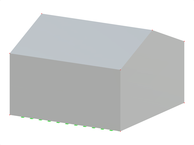
1. In "Types for Surface", define new "Additional Surface Result Points" on your RFEM model in the positions where the experimental probes were located on the real building/model. Select the surface and coordinates of the points and check the "Surface probe for wind analysis" option (Image 01, visible only when "Wind Simulation" is selected in the "Base Data" – "Add-ons" dialog box). Close the dialog box or go straight to the load case dialog box (if a wind analysis load case already exists).
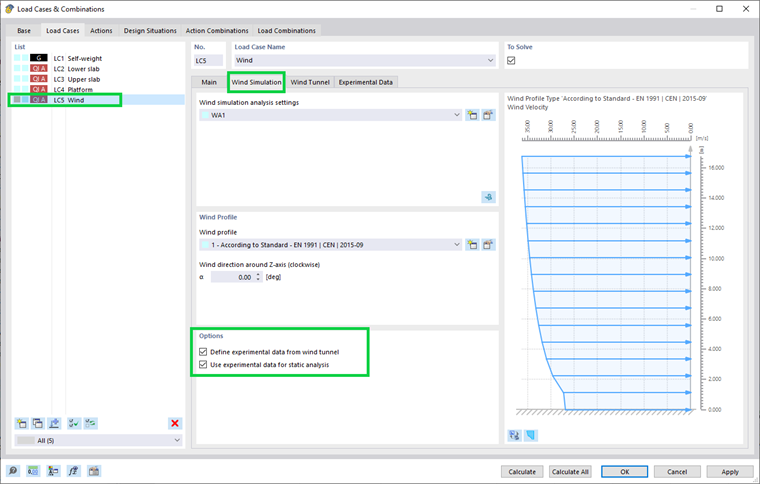
2. Open the load case dialog box, create a load case with the "Wind simulation" analysis type, and go to the "Wind Simulation" tab. In "Options", check "Define experimental data from wind tunnel". A new tab, "Experimental data", appears (Image 02).
If you want to use the experimental data for static analysis, check also the "Use experimental data for static analysis" option. (If you want to compare the results with the CFD calculation in RFEM 6, copy the load case and uncheck this second option.)
3. Even in situations when you are only defining the experimental data, the CFD calculation is performed in RWIND in order to create correct computational mesh and enable verification in RWIND 2. However, if you are interested only in static analysis based on the experimental data, the CFD wind simulation analysis settings can be reduced, and the convergence of the calculation does not have to be reached. Set a high convergence criterion or a low number of iterations.
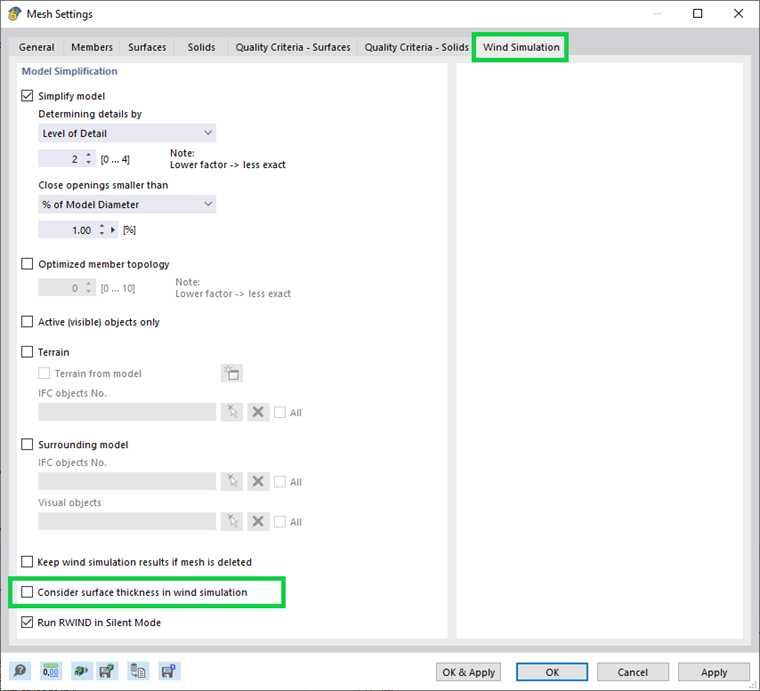
Note: Deactivate the option "Consider surface thickness in wind simulation" in the menu "Calculation" – "Mesh Settings" – "Wind Simulation" (Image 03). The probes are defined in the center line of the surfaces in RFEM. If the thickness cannot be neglected, you have to define the probe in RWIND in interactive mode and place it in the correct position on the surface.
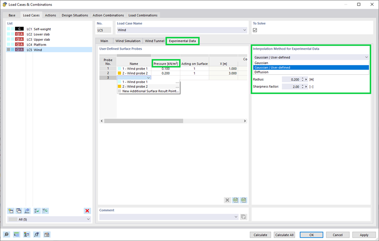
4. In the "Experimental data" tab, a table with additional surface result points for wind simulation is available. You can also create new probes here. In the column "Pressure", define the measured experimental pressures. In the column "Acting on Surface", a surface constraint for data interpolation can be prescribed specifically for each probe. However, in this program version, zones according to RFEM surfaces must be created in the RWIND interactive mode (an automatic assignment in silent mode will be implemented in a future version). If you want to use the silent RWIND mode, leave this column blank. The next columns describe the probe location (Image 04).
In the section "Interpolation method for data interpolation", select the interpolation method. The setting is valid for all probes. The recommendations of the appropriate method are described in Technical Article 1871 .
5. Calculate the load case.
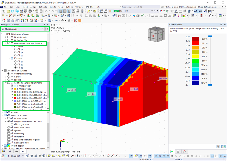
6. The static analysis is performed with loads calculated from the experimentally measured pressures. The load distribution can be checked in the "Result navigator" – "Static analysis" tab – "Distribution of loads" – "Load using RWIND and Ponding" (Image 05). The local pz value corresponds to the pressure on surface (for closed structures with zero inner pressure; more precisely, pz shows the difference of loads on both sides of the surface). Note that the local coordinate system must be oriented correctly. The "Wind simulation" tab shows the results from the associated CFD simulation.
7. If you want to compare the experimental data and CFD calculation, you can use RWIND interactive mode and compare the results in one load case (with the correct CFD simulation settings) or create separate load cases for the experimental (with reduced simulation settings) and CFD results and compare them in RFEM.
Conclusion
Wind-induced pressures measured on the surfaces of buildings and structures can be defined in RFEM 6, interpolated on surfaces in RWIND silent mode, and used again in RFEM 6 as wind load in static analysis. The results can be compared with the CFD calculation from RWIND.