
The initial stiffness Sj,ini is a decisive parameter for evaluating whether a connection can be characterized as rigid, non-rigid, or hinged.
In the “Steel Joints” add-on, you can calculate the initial stiffnesses Sj,ini according to Eurocode (EN 1993-1-8 Section 5.2.2) and AISC (AISC 360-16 Cl. E3.4) in relation to the internal forces N, My, and/or Mz.
The optional automatic transfer of initial stiffnesses allows for a direct transfer as member end hinge stiffnesses in RFEM. Then, the entire structure is recalculated and the resulting internal forces are automatically adopted as loads in the calculation and design of the connection models.
This automated iteration process eliminates the need for manual export and import of data, reducing the amount of work and minimizing potential sources of error.
Explanatory Video: Calculation of Initial Stiffness Sj,ini
- The design of the connection components is carried out according to AISC 360-16 and Eurocode EN 1993-1-8.
- After activating the add-on, the design situations for steel joints must be activated in the "Load cases and Combinations" dialog box.
- The "Structure Stability" add-on is required for the connection stability design (buckling).
- The calculation can be started via the table or the icon in the top bar.
The program supports you: It determines the bolt forces on the basis of the FE analysis model and evaluates them automatically. The add-on performs the standard-compliant design of bolt resistance for failure cases, such as tension, shear, hole bearing, and punching, and clearly displays all required coefficients.
Do you want to perform weld design? The welds are modeled as elastic-plastic surface elements, and their stresses are read out from the FE analysis model. The plasticity criteria is set in the way that they represent failure according to AISC J2-4, J2-5 (strength of welds), and J2-2 (strength of base metal). The design can be performed with the partial safety factors of the selected National Annex of EN 1993‑1‑8.
The plates in the connection are designed plastically by comparing the existing plastic strain to the allowable plastic strain. The default setting is 5% according to EN 1993‑1‑5, Annex C, but can be adjusted by user-defined specifications, as well as 5% for AISC 360.
_(2).png?mw=640&hash=0414bfe44045fc798e3774a0173332ca37424418)
General
- Beam to Column joint category: connection possible as joint of the beam to the column flange as well as joint of the column to the girder flange
- Beam to Beam joint category: design of beam joints as both moment-resisting end plate connections and rigid splice connections possible
- Automatic export of model and load data possible from RFEM or RSTAB
- Bolt sizes from M12 to M36 with strength grades 4.6, 4.8, 5.6, 5.8, 6.8, 8.8, and 10.9 as long as the strength grades are available in the selected National Annex
- Almost any bolt spacing and edge distances (a check of the allowable distances is performed)
- Beam strengthening with tapers or stiffeners on the top and bottom surfaces
- End plate connection with and without overlap
- Connection with pure bending stress, pure normal force load (tension joint), or combination of normal force and bending possible
- Calculation of connection stiffnesses and check if a hinged, semi-rigid, or rigid connection exists
End plate connection in a beam-column setup
- Joint beams or columns can be stiffened with tapers on one side or with stiffeners to one or both sides
- Wide range of possible stiffeners of the connection (for example, complete or incomplete web stiffeners)
- Up to ten horizontal and four vertical bolts possible
- Connected object possible as constant or tapered I-section
- Designs:
- Ultimate limit state of the connected beam (such as shear or tension resistance of the web plate)
- Ultimate limit state of the end plate at the beam (for example, T-stub under tensile stress)
- Ultimate limit state of the welds at the end plate
- Ultimate limit state of the column in the area of the connection (for example, column flange under bending – T-stub)
- All designs are performed according to EN 1993-1-8 and EN 1993-1-1
Moment-resisting end plate joint
- Two or four vertical and up to 10 horizontal bolt rows
- Joint beams can be stiffened with tapers on one side or with stiffeners to one or both sides
- Connected objects are possible as constant or tapered I-sections
- Designs:
- Ultimate limit state of the connected beams (such as shear or tension resistance of the web plates)
- Ultimate limit state of the end plates at the beam (for example, T-stub under tensile stress)
- Ultimate limit state of the welds at the end plates
- Ultimate limit state of the bolts in the end plate (combination of tension and shear)
Rigid splice plate connection
- For the flange plate connection, up to ten bolt rows one behind the other possible
- For the web plate connection, up to ten bolt rows possible each in vertical and horizontal directions
- Material of the cleat can be different from the one of the beams
- Designs:
- Ultimate limit state of the joint beams (for example, net cross-section in the tension area)
- Ultimate limit state of the cleat plates (for example, net cross-section under tensile stress)
- Ultimate limit state of the single bolts and the bolt groups (for example, shear resistance design of the single bolt)

- Design of knee joints, T-joints, cross joints, and continuous column connections with I-shaped sections
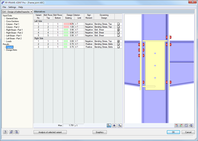
- Import of geometry and load data from RFEM/RSTAB or manual specification of the connection (for example, for recalculation without an existing RFEM/RSTAB model)
- Flush top connections or connections with bolt row in extension
- Design of positive and negative frame joint moments
- Various inclinations of right and left horizontal beams as well as application to frames of duopitch and monopitch roofs
- Consideration of additional flanges in a horizontal beam, for example for tapered sections
- Symmetrical and asymmetrical T-joints or cross joints
- Two-sided connection with different cross-section depth on the right and left
- Automatic preliminary design of bolt layout and required stiffening
- Optional design mode with possibility to specify all bolt spacing, welds, and sheet thicknesses
- Screwability check with adjustable dimensions of used wrenches
- Connection classification by stiffness and calculation of the spring stiffness of connections considered in the internal forces determination
- Check up to 45 individual designs (components) of the connection
- Automatic determination of governing internal forces for each individual design
- Controllable connection graphics in rendering mode with specifications of material, sheet thickness, welds, bolt spacing, and all dimensions for construction
- Integrated and flexibly extensible settings of National Annexes according to EN 1993-1-8 standard
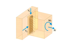
- Automatic conversion of internal forces from structural analysis into respective sections, also for eccentric member connections
- Automatic determination of initial stiffness Sj,ini of the connection
- Detailed plausibility check of all dimensions, including specifications of input limits (for example, for edge distances and hole spacing)
- Optional application of compression forces to a column through contact
- Possibility to update the cross-section depth of horizontal beams in case of tapered connections after connection geometry optimization in RF-/FRAME-JOINT Pro
The RF-/FRAME-JOINT Pro add-on module performs the following designs according to the standards EN 1993-1-8 or DIN 18800:
- Beam end plate and column flange according to the plastic hinge theory
- Tension of bolts (including contact forces)
- Shearing of bolts
- Tension force introduction in column web and beam web
- Buckling analysis of gusset plate
- Shear design of gusset plate
- Compression force introduction in column web and buckling design of web plate
- If required:
- Design of diagonal stiffeners
- Web stiffener
- Supplementary web plates
- Compression force introduction in horizontal beam
- Design of welds
- Design of member ends, members, nodal supports, nodes, and surfaces
- Consideration of specified design areas
- Check of cross-section dimensions
- Design according to EN 1995-1-1 (European Timber Standard) with the respective National Annexes + DIN 1052 + DSTV DIN EN 1993-1-8 + ANSI / AWC - NDS 2015 (US Standard)
- Design of various materials, such as steel, concrete, and others
- No necessary linking to specific standards
- Extensible library including timber fasteners (SIHGA, Sherpa, WÜRTH, Simpson StrongTie, KNAPP, PITZL) and steel fasteners (standardized connections in steel building design according to EC 3, M-connect, PFEIFER, TG-Technik)
- Ultimate load capacities of timber beams by the companies STEICO and Metsä Wood available in the library
- Connection to MS Excel
- Optimization of connecting elements (the most utilized element is calculated)