
In the RFEM add-on Surface Concrete Design allows you to perform the fire design according to the simplified table method (EN 1992-1-2, Chapter 5.4.2 and Table 5.8 and 5.9) for walls and ceilings made of reinforced concrete.

In the https://www.dlubal.com/en-US/products/rfem-fea-software/add-ons-for-rfem-6/design/stress-strain-analysis stress-strain add-on, you can define a component-dependent limit stress cycle and consider it for the design.

In RFEM, the oriented strand board (OSB) material is available for the USA and Canada. The material parameters are taken from the "Panel Design Specification manual".
- Full integration in RFEM/RSTAB with import of relevant internal forces
- Design checks for the elastic-elastic and elastic-plastic methods
- Graphical selection of members and sets of members for design
- Analysis for several load and design cases
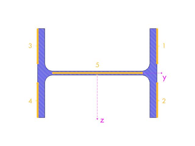
- Design based on the buckling field parameters integrated in the cross-section library for the cross-section parts supported on one and both sides
- Optional determination of shear stresses according to comment on El. (745)
- Possibility to consider the weld thickness in the design of welded cross-sections, which has the effect of a shortening of the cross-section part width
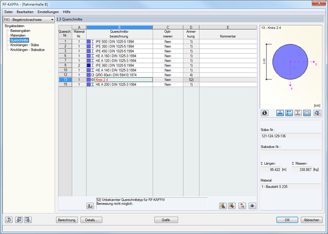
- Cross-section optimization with the option to export modified cross-sections

In RFEM, you can generate surfaces from members with the library cross-sections as well as from the members with the RSECTION cross-section.

In RFEM and RSTAB, you can visualize the flow field quantities of pressure, velocity, turbulence kinetic energy, and turbulence dissipation rate for the wind simulation.
The clipping planes are aligned with the respective wind direction.

Lines can be imported into RFEM either as lines or members. The names of layers are adopted as the cross-section names, and the first material from the predefined materials is assigned. However, if the section of the Dlubal cross-section library and the material are recognized from the layer name, they are adopted as well.
- Full integration in RFEM/RSTAB including import of all relevant internal forces
- Intelligent presetting of flexural buckling-specific design parameters
- Automatic determination of the distribution of internal forces and classification according to DIN 18800, Part 2
- Optional import of buckling lengths from the RF-STABILITY/RSBUCK add-on module. For this, a comfortable graphical selection of the relevant buckling mode is possible
- Optimizing Cross-Sections
- Optional calculation according to both design methods of DIN 18800, Part 2
- Automatic determination of the most unfavorable design location, also for tapered members
- Check of c/t-limit values according to DIN 18800, Part 1
- Design of any thin-walled RFEM/RSTAB or SHAPE-THIN section for compression and bending without interaction according to the elastic-plastic method
- Design of I-shaped rolled and welded sections, I-like sections, box sections, and pipes subjected to bending and compression with iteration according to the elastic-plastic method
- Clearly arranged, comprehensible design checks with all intermediate values in the short and long forms
- Parts list of members and sets of members
- Direct export of all results to MS Excel
- A manual with manually calculated examples
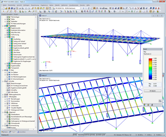
After the design, the results are displayed in different windows sorted by cross-sections, members, sets of members, or x-locations. The corresponding cross-section graphic is always displayed with the result values in tables. In RFEM/RSTAB, they are highlighted by different colors in the structural model. Critical or oversized components can be identified at a glance. You can modify the colors and values assigned.
Result diagrams of a member or a set of members ensure targeted evaluation. It is also possible to represent all intermediate values.
The masses determined during the design are displayed in parts lists for both members and sets of members.
Furthermore, you can export all result tables to MS Excel or in a CSV file. A special transfer menu defines all specifications required for the export.
- Automatic import of internal forces from RFEM/RSTAB
- Optional consideration of creep
- Automatic determination of planned and unintentional eccentricity from the second-order analysis in addition to the existing eccentricity
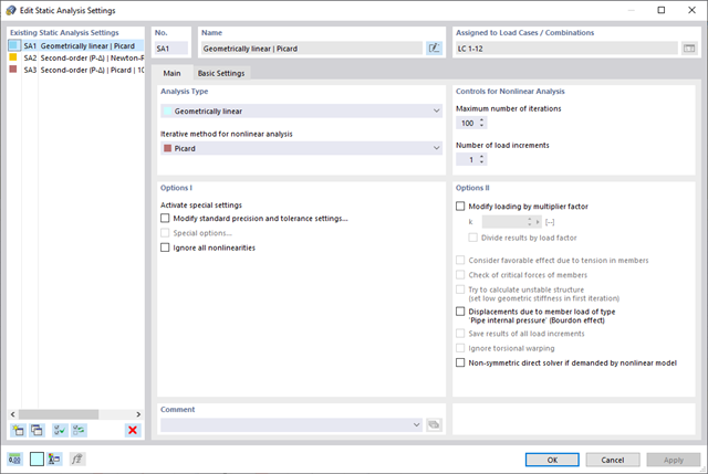
- Determination of internal forces according to the linear static analysis and the second-order analysis
- Analysis of governing design locations along the column due to existing loading
- Output of the required longitudinal and stirrup reinforcement
- Summary of design ratios, including all design details

- Import of relevant information and results from RFEM
- Integrated, editable material and section library
- Sensible and complete presetting of input parameters
- Punching design on columns (all section shapes), wall ends, and wall corners
- Automatic recognition of the punching node position from an RFEM model
- Detection of curves or splines as a boundary of the control perimeter
- Automatic consideration of all slab openings defined in the RFEM model
- Construction and graphical display of the control perimeter
- Optional design with unsmoothed shear stress along the control perimeter that corresponds to the actual shear stress distribution in the FE model
- Determination of the load increment factor β via full-plastic shear distribution as constant factors according to EN 1992‑1‑1, Sect. 6.4.3 (3), based on EN 1992‑1‑1, Fig. 6.21N, or by a user‑defined specification
- Numerical and graphical display of results (3D, 2D, and in sections)
- Punching design of the slab without punching reinforcement
- Qualitative determination of the required punching reinforcement
- Design and analysis of the longitudinal reinforcement
- Complete integration of results in an RFEM printout report
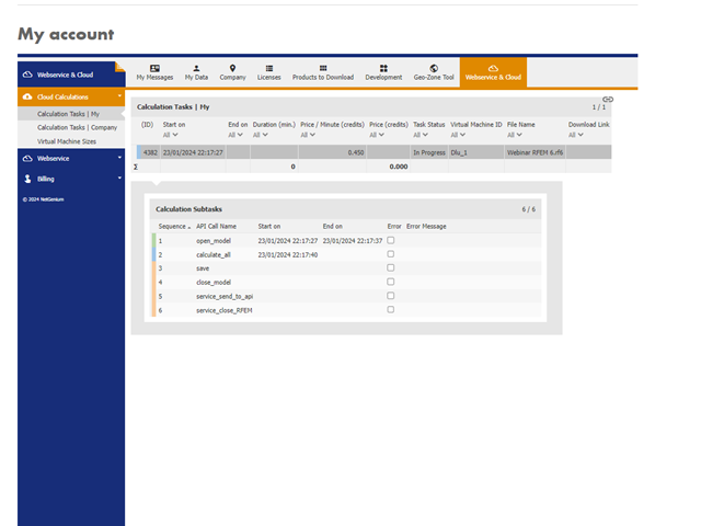
After completing the calculation, you will receive an email with a link to download the calculated file. Large files are compressed into a ZIP archive. Smaller files can be downloaded directly.
As an alternative, there is a link to the calculated file in the Extranet.
The downloaded file is a common RFEM file and can be used for further processing as usual.

If you have experimentally determined surface pressures available for a model, you can apply them to a structural model in RFEM 6, process them in RWIND 2, and use them as wind loads in the structural analysis of RFEM 6.
You can find out how to apply the experimentally determined values in this technical article.
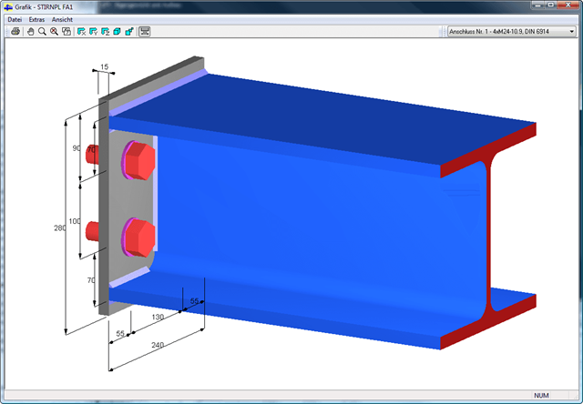
All design results and design checks are displayed in detail and in a comprehensible manner. An error log indicates non-designable situations or failed recommendations. Due to the permanent integration in RFEM/RSTAB, subsequent modifications in the structural system and in loading are automatically taken into account for the connections to be checked.
If one of the designs could not be fulfilled, the corresponding line is highlighted in red. The output appears in a short or a long form in the global printout report of RFEM/RSTAB. Furthermore, you can easily export all result tables to MS Excel or in a CSV file. A special transfer menu defines all specifications required for the export.

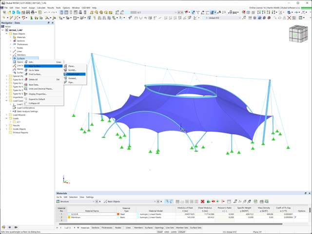
The combination wizard provides you with the option to consider more than one initial state. RFEM and RSTAB allow you to specify different initial states (prestress, form-finding, strain, and so on) for the target combinations in the combinatorics.
You can thus, for example, generate load states on the basis of a form-finding analysis with varying imperfections.
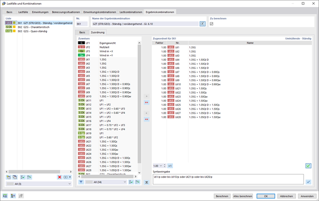
Rely on RFEM 6 even in the case of result combinations. First, you can have the contained load cases calculated in the result combinations. Then, the results are superimposed by taking into account the corresponding factors. In the result combinations, you can superimpose the results of load cases, load combinations, and other result combinations. Internal forces are added together by default. However, you have the option of a square addition, which is relevant for dynamic analysis.

In the Geotechnical Analysis add-on, the Hoek-Brown material model is available. The model shows linear-elastic ideal-plastic material behavior. Its nonlinear strength criterion is the most common failure criterion for stone and rocks.
You can enter the material parameters using
- Rock parameters directly, or alternatively via
- GSI classification.
Detailed information about this material model and the definition of the input in RFEM can be found in the respective chapter Hoek-Brown Model of the online manual for the Geotechnical Analysis add-on.

As soon as the program has completed the calculation, the summary of the results is listed. All result windows are integrated in the main program RFEM/RSTAB. You will find all the results arranged in tables; they can be displayed for each individual time step or as an envelope, and you also have the option of displaying the results graphically as well as animating them.
The results from the time history analysis can be displayed in the calculation diagrams. All the results are shown as a function of time. You can export the numeric values to MS Excel.
All result tables and graphics are part of the RFEM/RSTAB printout report. In this way, you can ensure clearly arranged documentation. You can also export the tables to MS Excel.
The program does a lot of work for you. The members to be designed are directly imported from RFEM/RSTAB.
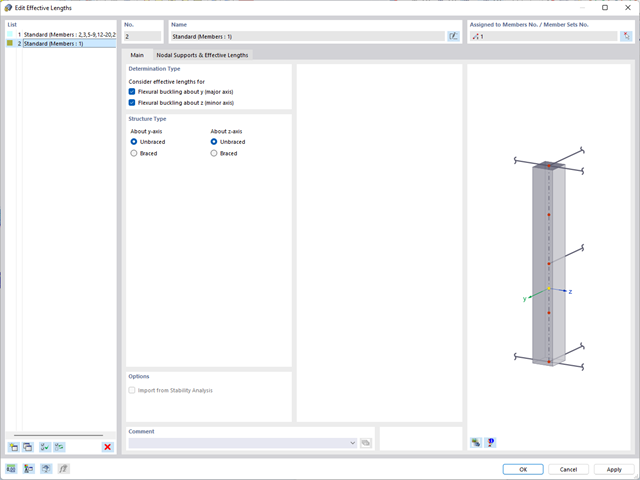
You can easily define constructional properties of columns as well as other details for determining the required longitudinal and shear reinforcement. In this case, you can manually define the effective length factor ß or import it from the Structure Stability add-on.

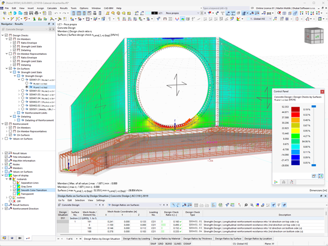
Have you carried out the design successfully? The results of the deformation analysis are now listed in clearly arranged output tables or detailed dialog boxes with info text. The program shows you all intermediate values in a comprehensible manner. Graphical representation of design ratios and deformation in RFEM allows you for a quick overview of critical areas.
Due to the results output of the design checks with all intermediate results, you can follow the calculation to the smallest detail. The complete integration of results in the RFEM printout report ensures that you obtain verifiable structural design.

Do you have individual column sections and angled wall geometries, and need punching shear design for them?
No problem. In RFEM 6, you can perform punching shear design not only for rectangular and circular sections, but for any cross-section shape.
A great strength of the Dlubal programs is their intuitive, easy-to-learn operation. RFEM 6 is no exception. Create your structure in a user interface usual for CAD or via tables. By right-clicking the graphical or navigator objects, a shortcut menu appears, which facilitates you creating or editing the objects. Due to the intuitive user interface, you can create structural and loading objects in a very short time.
Go to Explanatory Video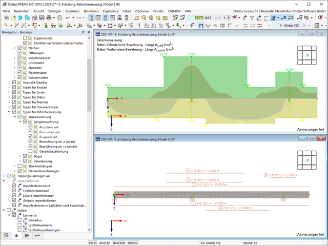
- Deformation analyses of reinforced concrete surfaces without or with cracks (state II) by applying the approximation method (for example, deformation analysis according to ACI 318-19, 24.3.2.5 or EN 1992‑1‑1, Cl. 7.4.3 )
- Tension stiffening of concrete applied between cracks
- Optional consideration of creep and shrinkage
- Graphical representation of results integrated in RFEM, such as deformation or sag of a flat slab
- Clear numerical result display in the detail dialog box
- Complete integration of results in the RFEM printout report
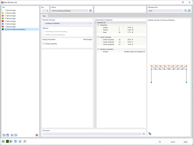
Planning with members is also facilitated in the programs due to specific features. You can arrange members eccentrically, support them by elastic foundations, or define them as rigid links. Member sets allow you to easily apply the load on several members.
In RFEM, you can also define eccentricities of surfaces. Here, you can transform nodal and linear loads into surface loads. If necessary, divide surfaces into surface components and members into surfaces.
This feature helps you with the load application. You can have the required loading applied incrementally. This option is particularly suitable for your calculations according to the large deformation analysis. Furthermore, you can easily perform post‑critical analyses in RFEM.

The program does a lot of work for you. For example, the load or result combinations required for the serviceability limit state are generated and calculated in RFEM/RSTAB. You can select these design situations for the deflection analysis in the Aluminum Design add-on. Depending on the specified precamber and reference system, the program determines the deformation values at each location of a member. They are then compared to the limit values.
You can specify the deformation limit value individually for each structural component in Serviceability Configuration. In this case, you define the maximum deformation depending on the reference length as the allowable limit value. By defining design supports, you can segment the components. In this way, you can determine the corresponding reference length automatically for each design direction.
And that's not all. Based on the position of the assigned design supports, the program allows you to automatically determine the distinction between beams and cantilevers. The limit value is thus determined accordingly.

Building stone on stone has a long tradition in construction. The Masonry Design add-on for RFEM allows you to design masonry using the finite element method. It was developed as part of the research project DDMaS - Digitizing the Design of Masonry Structures. Here, the material model represents the nonlinear behavior of the brick-mortar combination in the form of macro-modeling. Do you want to find out more?

You can find the serviceability limit state design checks in the result tables of the Aluminum Design add-on. They are already fully integrated there. You have the option to display the design results with all the details at each location of the designed members. You can also use graphics with the result diagrams of the design ratios.
You can integrate all result tables and graphics into the global printout report of RFEM/RSTAB as a part of the aluminum design results. RFEM/RSTAB also allows you to display and document the deformations of the entire structure independently of the add-on.

- Calculation of deflections and comparison with the normative or manually adjusted limit values
- Consideration of a precamber for the deflection analysis
- Different limit values are possible, depending on the design situation type
- Manual adjustment of reference lengths and segmentation by direction
- Calculation of deflections related to the initial structure or to the deformed structure
- Further detailed design checks depending on the selected design standard (for example, limitation of web breathing according to EN 1993‑2)
- Graphical result display integrated in RFEM/RSTAB; for example, the design ratio of a limit value, the deformation, or the sag
- Complete integration of the results into the RFEM/RSTAB printout report

For each load case, the deformations can be displayed at the end time.
These results are also documented for you in the printout report of RFEM and RSTAB. You can select the report contents and extent specifically for the individual design checks.