
The Ponding load type allows you to simulate rain actions on multi-curved surfaces, taking into account the displacements according to the large deformation analysis.
This numerical rainfall process examines the assigned surface geometry and determines which rainfall portions drain away and which rainfall portions accumulate in puddles (water pockets) on the surface. The puddle size then results in a corresponding vertical load for the structural analysis.
For example, you can use this feature in the analysis of approximately horizontal membrane roof geometries subjected to rain loading.
Go to Explanatory Video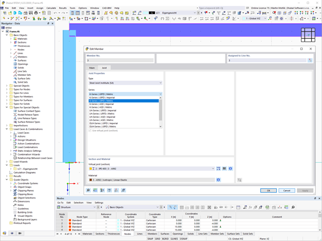
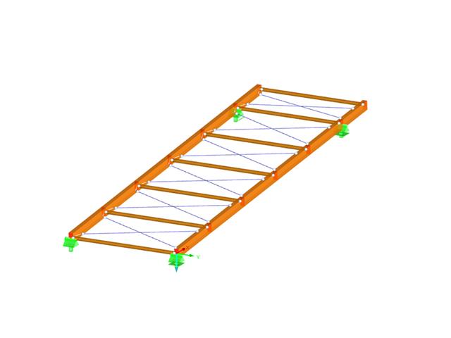
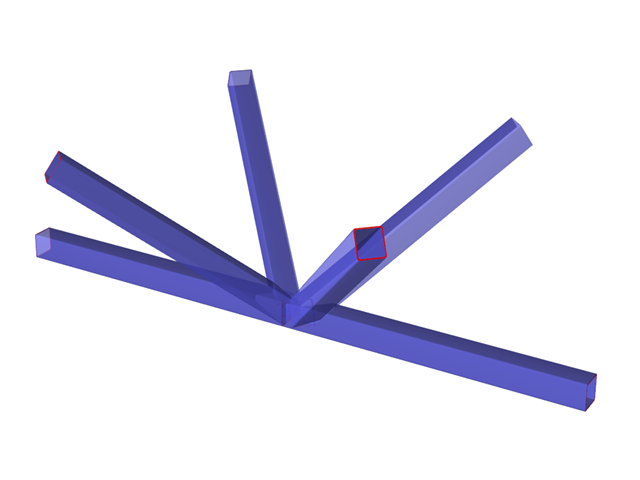
The "Virtual Joist" member type allows you to simulate prefabricated beams in a global model. The beam is replaced by a member with a virtual section.
This function makes it easier for you to simulate complex supporting units, such as a truss girder, in the overall system.

Can you use some support? The "surface model" member type helps you to simulate a member as a surface model in the overall model.
This feature provides you with the following:
- Quick input using a member with a cross-section
- Simulation of openings in the web
- Simultaneous output of the member and surface results
- Design of member results in the add-on
- Consideration of a real stress distribution
You can use the surface member for the following applications, among others:
- Castellated beams
- Perforated beams
- Beams with rectangular openings
- Vierendeel trusses

- Many predefined components: Allow easy input of typical connection situations, such as end plates, angles, multi-wall sheets, cleats, fin plates
- Universally applicable basic components (plates, welds, bolts, auxiliary planes) for entering complex connection situations
- Graphical display of the connection geometry that is updated in parallel with the input
- The Steel Joints Template included in the add-on allows you to select from several connection types and, and once selected, it will be applied to your model.
- Wide range of cross-section shapes: Includes I-sections, channel sections, angles, T-sections, built-up cross-sections, RHS (rectangular hollow sections), and thin-walled sections
- The Template covers connections from three general categories: Rigid, Pinned, Truss
- Automatic adaptation of the connection geometry, even if the structural components are subsequently edited, based on the relative relation of the components
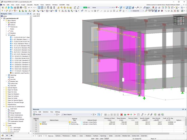
Keep an eye on all surfaces. A surface with the "Load Transfer" stiffness type has no structural effect. You can use it to consider the loads from surfaces that have not been modeled, for example, facade structures, glass surfaces, trapezoidal roof sections, and so on.
Go to Explanatory Video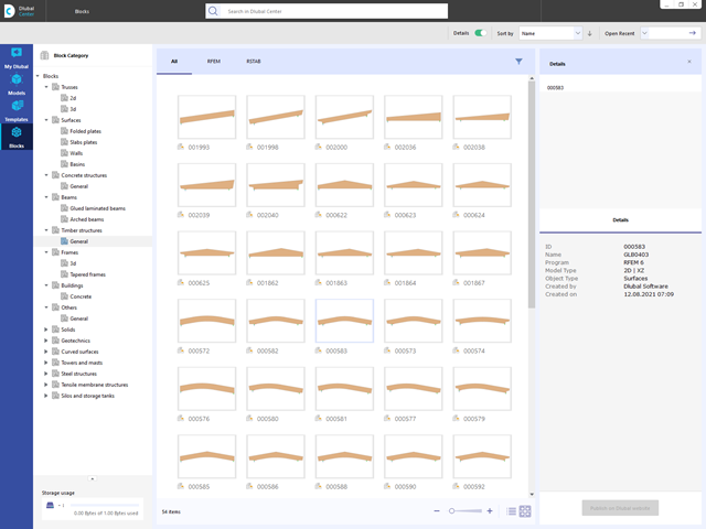
Are you looking for models for your design? Then you have come to the right place at the Dlubal Center. It contains an extensive database with partly parameterized models. These include, for example, trusses, glulam beams, tapered frames, or tower segments. You can import these models and, if necessary, modify them according to your individual requirements. Furthermore, you can save the models as a block for later use.
_ENG.png?mw=640&hash=1053c9bef400e9f5361c9c3278f76a272fcc4ddf)
Have you activated the Time-Dependent Analysis (TDA) add-on? Very well, now you can add time data to load cases. After you have defined the start and end of the load, the influence of creep at the end of the load is taken into account. The program allows you to model creep effects for frame and truss structures made of reinforced concrete.
In this case, the calculation is performed nonlinearly according to the rheological model (Kelvin and Maxwell model).
Was the calculation successful? You can now display the determined internal forces in tables and graphics, and consider them in the design.
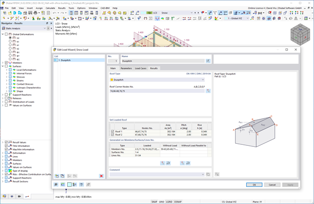
Do you want your structures to remain upright even in wind and snow? Then rely on the load wizards for plate and frame structures. You can now generate wind loads according to EN 1991‑1‑4 and snow loads according to EN 1991‑1‑3 (as well as other international standards). The load cases are generated depending on the roof shape.

Wind loads are also not a problem in your design. You can automatically generate wind loads as member loads or area loads (RFEM) on the following structural components:
- Vertical walls
- Flat roofs
- Monopitch roofs
- Duopitch/troughed roofs
- Vertical walls with duopitch roof
- Vertical walls with flat/monopitch roof
The following standards are available to you:
-
 EN 1991-1-4 (including National Annexes)
 -
 ASCE 7
 -
 CTE DB-SE-AE
 -
 GB 50009
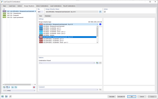
For the combination of actions, you have come to the right place. If you use them in the ultimate and the serviceability limit state, you can select various design situations according to the standard (for example, ULS (STR/GEO) - permanent/transient, SLS - quasi-permanent, and others). Optionally, you can also integrate imperfections in the combination and determine load cases that should not be combined with other load cases (for example, construction load for roof not combined with snow load).
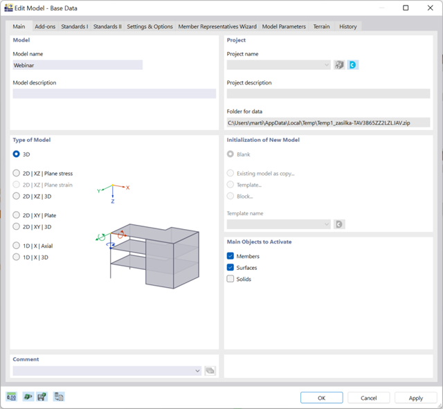
There are many options available for simple input and modeling. Your model is entered as a 1D, 2D, or 3D model. Member types such as beams, trusses, or tension members make it easier for you to define member properties. In order to model surfaces, RFEM provides you with various types, such as Standard, Without Thickness, Rigid, Membrane, and Load Distribution.
Furthermore, RFEM covers various material models, such as Isotropic | Linear Elastic, Orthotropic | Linear Elastic (Surfaces, Solids), or Isotropic | Timber | Linear Elastic (Members).
.png?mw=640&hash=9aa98962d5e0d0ed2803b35fcb6a2f87288b0946)
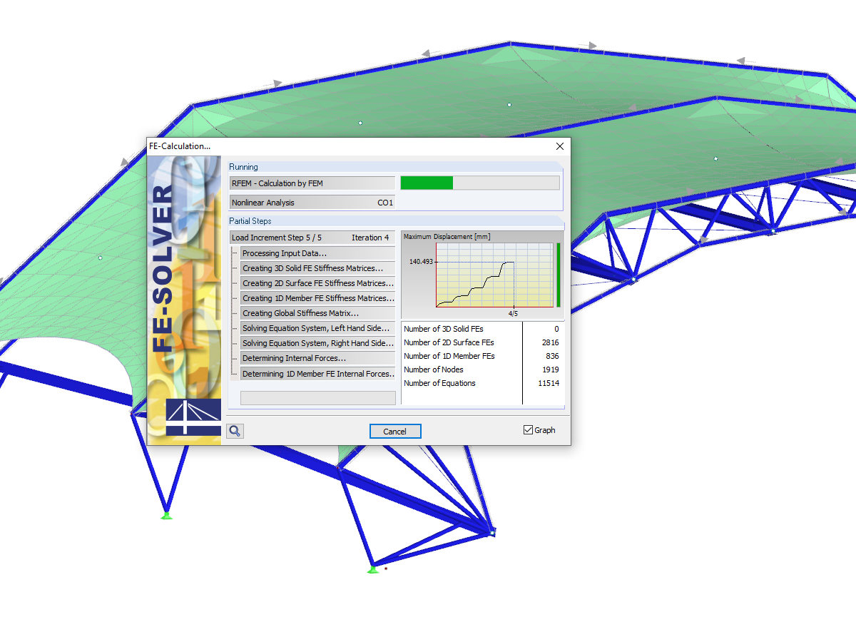
The number of degrees of freedom in a node is no longer a global calculation parameter in RFEM (6 degrees of freedom for each mesh node in 3D models, 7 degrees of freedom for the warping torsion analysis). Thus, each node is generally considered with a different number of degrees of freedom, which leads to a variable number of equations in the calculation.
This modification speeds up the calculation, especially for models where a significant reduction of the system could be achieved (for example, trusses and membrane structures).
- Design of the following roof types:
- Monopitch roof
- Duopitch Roof
- Curved roof
- All roof shapes allow for a free selection of stiffening diagonals. The following types are available:
- Falling diagonals
- Rising diagonals
- Crossing diagonals with verticals
- Crossing diagonals without verticals
- Crossing diagonals with steel strips (ties)
- Consideration of window rows in the ridge by selecting an inner intermediate part.
- For design according to EC 5 (EN 1995), the following National Annexes are available:
-
 DIN EN 1995-1-1/NA:2013-08 (Germany)
 -
 NBN EN 1995-1-1/ANB:2012-07 (Belgium)
 -
 DK EN 1995-1-1/NA:2011-12 (Denmark)
 -
 SFS EN 1995-1-1/NA:2007-11 (Finland)
 -
 NF EN 1995-1-1/NA:2010-05 (France)
 -
 UNI EN 1995-1-1/NA:2010-09 (Italy)
 -
 NEN EN 1995-1-1/NB:2007-11 (Netherlands)
 -
 ÖNORM B 1995-1-1:2015-06 (Austria)
 -
 PN EN 1995-1-1/NA:2010-09 (Poland)
 -
 SS EN 1995-1-1 (Sweden)
 -
 STN EN 1995-1-1/NA:2008-12 (Slovakia)
 -
 SIST EN 1995-1-1/A101:2006-03 (Slovenia)
 -
 CSN EN 1995-1-1:2007-09 (Czech Republic)
 -
 BS EN 1995-1-1/NA:2009-10 (the United Kingdom)
-
- Simple geometry input with illustrative graphics
- Automatic generation of wind loads
- Automatic creation of required combinations for the ultimate and serviceability limit states, as well as fire resistance design
- Free definition of the load cases to be used
- Extensive material library
- Optional extension of material library by further materials
- Extensive library of permanent loads
- Allocation of framework to service classes and specification of service class categories
- Determination of design ratios, support forces, and deformations
- Info icon indicating successful or failed design
- Color reference scales in result tables
- Direct data export to MS Excel
- DXF interface for preparation production documents in CAD
- Program languages: English, German, Czech, Italian, Spanish, French, Portuguese, Polish, Chinese, Dutch, and Russian
- Verifiable printout report, including all required designs. Printout report available in many output languages; for example, English, German, French, Italian, Spanish, Russian, Czech, Polish, Portuguese, Chinese, and Dutch.
- In the ultimate limit state design, the stiffness of the hinge is divided by the partial safety factor and in the serviceability limit state design calculated using the mean stiffnesses. The limit values for the ultimate and the serviceability limit states can be defined separately.
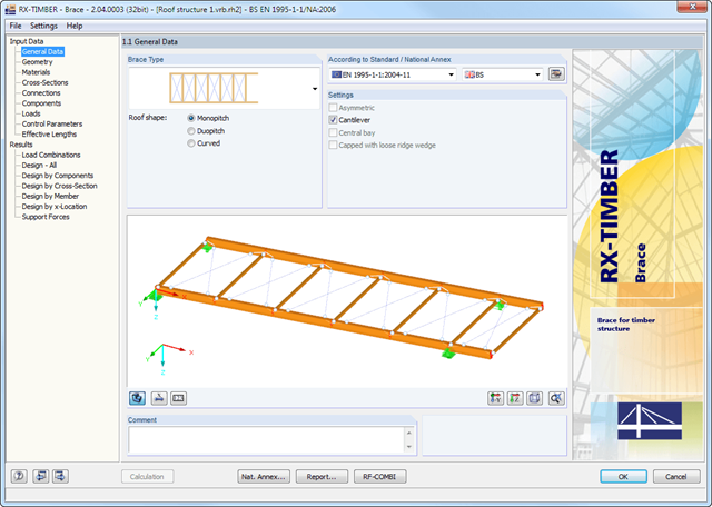
The geometry is entered by means of templates, as in all other programs of the RX‑TIMBER family. By selecting the roof structure, you define the base geometry, which can be adjusted by user-defined settings. The relevant timber grade of the material can be selected from the material library. All material grades for glulam, hardwood, poplar and softwood timber specified in EN 1995-1-1 are available. Furthermore, it is possible to generate a strength class with user-defined material properties in order to extend the library.
Since the stiffening bracing includes the steel cross-sections, current steel grades are integrated in the library as well. Therefore, rolled and welded cross-sections are also available. Stiffening of coupling elements can be considered in Table 1.5 Connections as translational and rotational spring stiffnesses. The program handles these stiffnesses with a stiffness divided by the partial safety factor for the design of the bearing capacity and with the mean values of the stiffness for the serviceability limit state design. The loading can be entered directly as a lateral load (equivalent lateral load) resulting from a truss girder design.
The wind load is applied automatically to all four sides of the structure. Additionally, you can specify user-defined loads; for example, concentrated loads from columns (buckling load). According to the generated loads, the program automatically creates combinations for the ultimate and serviceability limit states as well as for fire resistance design in the background. The generated combinations can be considered or adjusted by user-defined specifications.
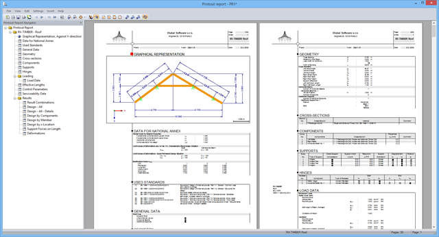
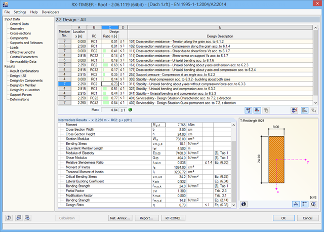
After the calculation, the results of performed designs, including all required intermediate values, are displayed in clearly arranged result tables sorted by various criteria. Since the program displays the intermediate values in detail, the transparency of all designs is ensured. It is possible to display the distribution of internal forces for each x-location of the beam in a separate graphical window. Here, both the deformations and the individual internal forces can be displayed.
Designs with design details and selected result diagrams can be added in the printout report, providing clearly arranged documentation. The printout report can include graphics, descriptions, drawings, and more. Moreover, it is possible to select which calculation data will be covered in the printout.
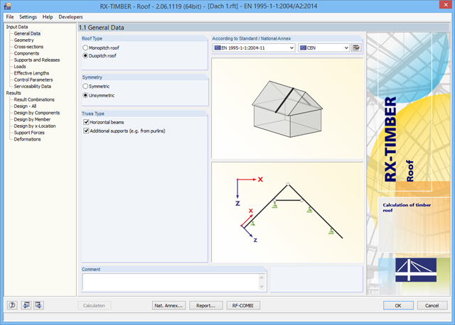
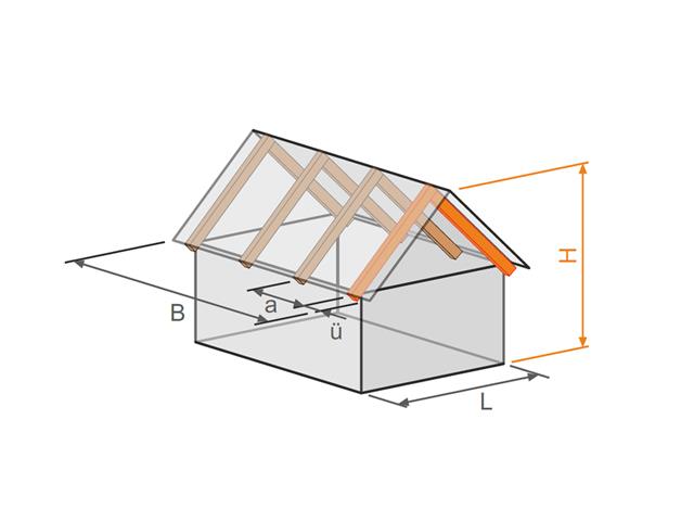
There are various options available for modeling a roof. Graphical representations facilitate the geometry input. Modifications are updated automatically.
In addition, it is possible to consider cross‑section weakening on supports. Optionally, you can define if the design of support pressure on the rafter side should be performed.
Permanent loads (for example, roof structure) can be entered using the comprehensive and extensible material library. Loads due to cantilevers and collars/ties can be entered separately. Generators integrated in RX-TIMBER Purlin allow for convenient generation of various wind and snow load cases. You can manually add any concentrated and distributed loads.
Load cases are displayed graphically and superimposed in automatically generated load combinations according to EC 5. For stability and serviceability limit state designs, you can change the data manually, for example, for example, for cantilevers (roof overhang), it is necessary to ignore the SLS.
- Design of the following roof types:
- Flat Roof
- Monopitch roof
- Duopitch roof (symmetrical/asymmetrical)
- Definition of any additional support and free selection of degrees of freedom (additional free definition of translational and rotational spring stiffness of supports and hinges)
- Arrangement of up to five collar/tie beams, including intermediate support for duopitch roof
- Automatic generation of wind and snow loads
- Automatic generation of required combinations for the ultimate and serviceability limit states, as well as fire resistance design (additional definition of several member and nodal loads)
- For design according to EC 5 (EN 1995), the following National Annexes are available:
-
Germany DIN EN 1995-1-1/NA:2013-08 (Germany)
-
NBN EN 1995-1-1/ANB:2012-07 (Belgium)
-
 BDS EN 1995-1-1/NA:2012-02 (Bulgaria)
 -
DK EN 1995-1-1/NA:2011-12 (Denmark)
-
SFS EN 1995-1-1/NA:2007-11 (Finland)
-
NF EN 1995-1-1/NA:2010-05 (France)
-
 I S. EN 1995-1-1/NA:2010-03 (Ireland)
 -
UNI EN 1995-1-1/NA:2010-09 (Italy)
-
NEN EN 1995-1-1/NB:2007-11 (Netherlands)
-
ÖNORM B 1995-1-1:2015-06 (Austria)
-
PN EN 1995-1-1/NA:2010-09 (Poland)
-
SS EN 1995-1-1 (Sweden)
-
STN EN 1995-1-1/NA:2008-12 (Slovakia)
-
SIST EN 1995-1-1/A101:2006-03 (Slovenia)
-
CSN EN 1995-1-1:2007-09 (Czech Republic)
-
BS EN 1995-1-1/NA:2009-10 (the United Kingdom)
-
 CYS EN 1995-1-1/NA:2011-02 (Cyprus)
-
- Simple geometry input with illustrative graphics
- Input of tapered cantilevers with cut-to-grain on the bottom side of rafters
- Extensive material library that can be extended by user-defined materials
- Determination of design ratios, support forces, and deformations
- Color reference scales in result tables
- Direct data export to MS Excel
- Program languages: English, German, Czech, Italian, Spanish, French, Portuguese, Polish, Chinese, Dutch, and Russian
- Verifiable printout report, including all required designs. Printout report available in many output languages; for example, English, German, French, Italian, Spanish, Russian, Czech, Polish, Portuguese, Chinese, and Dutch.
In RX-TIMBER Roof, you can set the following calculation specifications: *Selection of the designs to be performed (ULS, SLS, fire resistance)
- Determination of displaying support forces and deformations
- Adjusting the recommended limit values for the serviceability limit state
- Definition of parameters for fire resistance design according to the simplified method
- Increasing strengths according to EN 1995‑1‑1, Clause 3.2
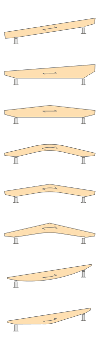
- Design of the following beam types:
- Parallel beam
- Monopitch roof beam
- Double tapered beam
- Arched beam
- Pitched cambered beam with constant height
- Pitched cambered beam with variable height
- Fish Beam - Parabolic
- Fish beam - Linear with rounding in central area
- Unsymmetrical beams with and without cantilevers
- Arrangement of a loose ridge wedge
- Optional consideration of stiffening elements for transversal tension
- Two design types available for stiffening elements concerning transversal tension:
- Constructive if required
- Full absorption of tension stresses perpendicular to grain
- Calculation of required number of stiffening elements for transversal tension and graphical representation of the arrangement in the beam
- Simple geometry input with illustrative graphics
- Convenient generation of snow loads according to EN 1991-1-3 or DIN 1055:2005, Part 5
- Automatic determination of wind loads according to EN 1991-1-4 or DIN 1055:2005, Part 4
- User-defined load cases and load applications
- Automatic generation of all possible load combinations
- Connection to MS Excel and access via COM interface
- Material library for both standards
- For design according to EC 5 (EN 1995), the following National Annexes are available:
-
DIN EN 1995-1-1/NA:2013-08 (Germany)
-
NBN EN 1995-1-1/ANB:2012-07 (Belgium)
-
DK EN 1995-1-1/NA:2011-12 (Denmark)
-
SFS EN 1995-1-1/NA:2007-11 (Finland)
-
NF EN 1995-1-1/NA:2010-05 (France)
-
UNI EN 1995-1-1/NA:2010-09 (Italy)
-
NEN EN 1995-1-1/NB:2007-11 (Netherlands)
-
ÖNORM B 1995-1-1:2015-06 (Austria)
-
PN EN 1995-1-1/NA:2010-09 (Poland)
-
SS EN 1995-1-1 (Sweden)
-
STN EN 1995-1-1/NA:2008-12 (Slovakia)
-
SIST EN 1995-1-1/A101:2006-03 (Slovenia)
-
CSN EN 1995-1-1:2007-09 (Czech Republic)
-
BS EN 1995-1-1/NA:2009-10 (the United Kingdom)
-
- Extensive library of permanent loads
- Allocation of a structure to service class, and specification of service class categories
- Determination of design ratios, support forces, and deformations
- Info icon indicating successful or failed design
- Color reference scales in result tables
- Direct data export to MS Excel
- DXF interface for preparation production documents in CAD
- Program languages: English, German, Czech, Italian, Spanish, French, Portuguese, Polish, Chinese, Dutch, and Russian
- Verifiable printout report, including all required designs. Printout report available in many output languages; for example, English, German, French, Italian, Spanish, Russian, Czech, Polish, Portuguese, Chinese, and Dutch.
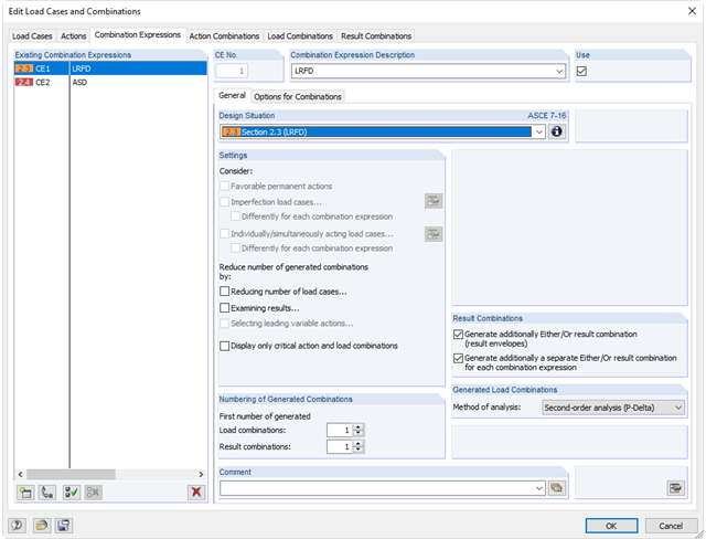
For the combination of actions in the ultimate and the serviceability limit state, you can select various design situations according to the standard (for example, ULS (STR/GEO) - permanent/transient, SLS - quasi-permanent, and others).
Furthermore, there is the option to integrate imperfections in the combination and to determine load cases that should not be combined with other load cases (for example, construction load for roof not combined with snow load).
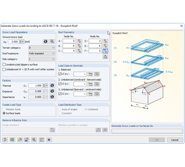
There are load generators available for beam structures, creating snow loads according to ASCE/SEI 7-10. The load cases are generated depending on the roof shape. Another generator creates coating loads (ice). You can save recurring load combinations as templates.
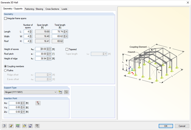
Generating tools to enter parametric models such as frames, halls, trusses, spiral stairways, arcs, or roofs. In addition, many generators allow for the creation of load cases and loading resulting from weight, snow, and wind.
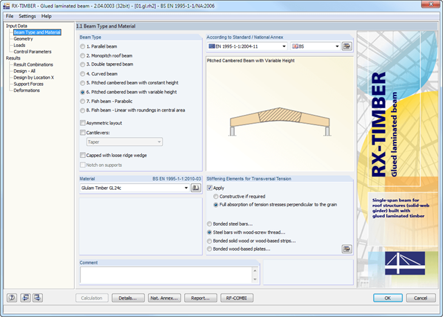
RX-TIMBER Glued-Laminated Beam designs wide-span glulam beams of eight different beam types (parallel, monopitch roof, double tapered beam, and others).
It is possible to consider typical stiffening elements for transversal tension; for example, bonded steel bars.
RX-TIMBER Glued-Laminated Beam | Design of Glued-Laminated Beams
- Design of knee joints, T-joints, cross joints, and continuous column connections with I-shaped sections
- Import of geometry and load data from RFEM/RSTAB or manual specification of the connection (for example, for recalculation without an existing RFEM/RSTAB model)
- Flush top connections or connections with bolt row in extension
- Design of positive and negative frame joint moments
- Various inclinations of right and left horizontal beams as well as application to frames of duopitch and monopitch roofs
- Consideration of additional flanges in a horizontal beam, for example for tapered sections
- Symmetrical and asymmetrical T-joints or cross joints
- Two-sided connection with different cross-section depth on the right and left
- Automatic preliminary design of bolt layout and required stiffening
- Optional design mode with possibility to specify all bolt spacing, welds, and sheet thicknesses
- Screwability check with adjustable dimensions of used wrenches
- Connection classification by stiffness and calculation of the spring stiffness of connections considered in the internal forces determination
- Check up to 45 individual designs (components) of the connection
- Automatic determination of governing internal forces for each individual design
- Controllable connection graphics in rendering mode with specifications of material, sheet thickness, welds, bolt spacing, and all dimensions for construction
- Integrated and flexibly extensible settings of National Annexes according to EN 1993-1-8 standard
- Automatic conversion of internal forces from structural analysis into respective sections, also for eccentric member connections
- Automatic determination of initial stiffness Sj,ini of the connection
- Detailed plausibility check of all dimensions, including specifications of input limits (for example, for edge distances and hole spacing)
- Optional application of compression forces to a column through contact
- Possibility to update the cross-section depth of horizontal beams in case of tapered connections after connection geometry optimization in RF-/FRAME-JOINT Pro
- Integration in RFEM/RSTAB with automatic geometry recognition and transfer of internal forces
- Optional manual definition of connections
- Extensive library of hollow sections for chords and struts:
- Round sections
- Square sections
- Rectangular sections
- Implemented steel grades: S 235, S 275, S 355, S 420, S 450, and S 460
- Various types of connections available, depending on the standard specifications:
- K connection (gap/overlapping)
- KK connection (spatial)
- N connection (gap/overlapping)
- KT connection (gap/overlapping)
- DK connection (gap/overlapping)
- T connection (planar)
- TT connection (spatial)
- Y connection (planar)
- X connection (planar)
- XX connection (spatial)
- Selection of partial safety factors according to the National Annex for Germany, Austria, Czech Republic, Slovakia, Poland, Slovenia, Switzerland, or Denmark
- Adjustable angles between struts and chords
- Optional chord rotation of 90° for rectangular hollow sections
- Consideration of gaps between struts or overlapping struts
- Optional consideration of additional nodal forces
- Design of the connection as the maximum load-bearing capacity of the struts of a truss for axial forces and bending moments
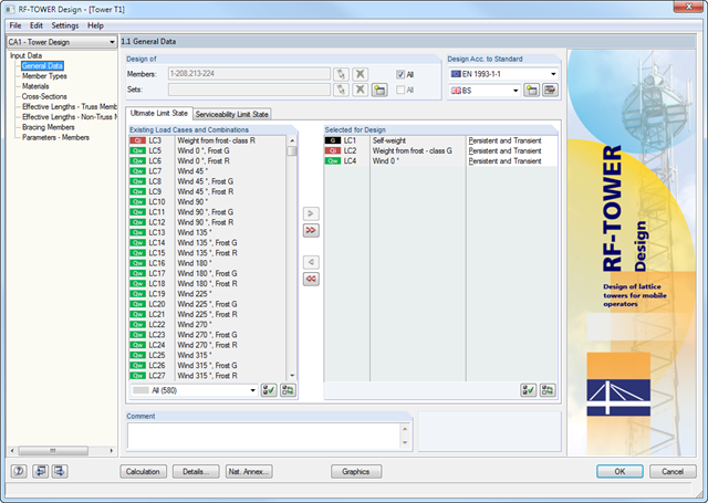
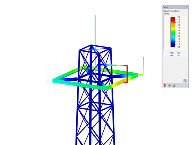
Members of triangular and quadrilateral lattice towers are allocated automatically, provided that the lattice tower was generated in the RF-/TOWER Structure and RF-/TOWER Equipment add-on modules.
However, it is also possible to allocate the members manually. In RF-/TOWER Design, you can use the effective lengths of truss members generated in the RF-/TOWER Effective Lengths add-on module. Manual input is also possible.
According to the EN 1993-3-1 and EN 50341 standards, different bracing cases and support types can be specified for the leg members and bracing members.
- Consideration of the data from the other RF-/TOWER modules (Structure, Equipment, Loading, Effective Lengths)
- Automatic cross-section classification
- Design of triangular and quadrilateral lattice towers according to EN 1993-1-1, EN 1993-3-1, and EN 50341, including National Annexes
- Flexural buckling analysis of truss members based on the effective slenderness considering bracing and support conditions
- Design of equipment such as platforms according to EN 1993-1-1
- Clearly arranged display of results including relevant parameters in result tables
- Parts list result window
- Creation of a verifiable printout report
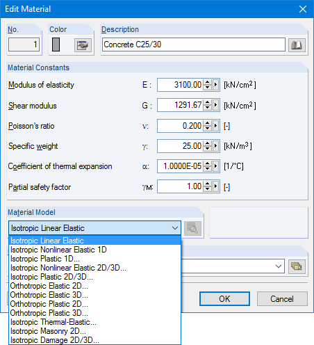
Structures are entered as 1D, 2D, or 3D models. Member types such as beams, trusses, or tension members facilitate the definition of member properties. For modeling surfaces, RFEM provides For example, the types Standard, Orthotropic, Glass, Laminate, Rigid, Membrane, and so on, are available.
Furthermore, RFEM can select among the material models Isotropic Linear Elastic, Isotropic Plastic 1D/2D/3D, Isotropic Nonlinear Elastic 1D/2D/3D, Orthotropic Elastic 2D/3D, Orthotropic Plastic 2D/3D (Tsai-Wu 2D/3D), and Isotropic Thermal -elastic, Isotropic Masonry 2D, and Isotropic Damage 2D/3D.
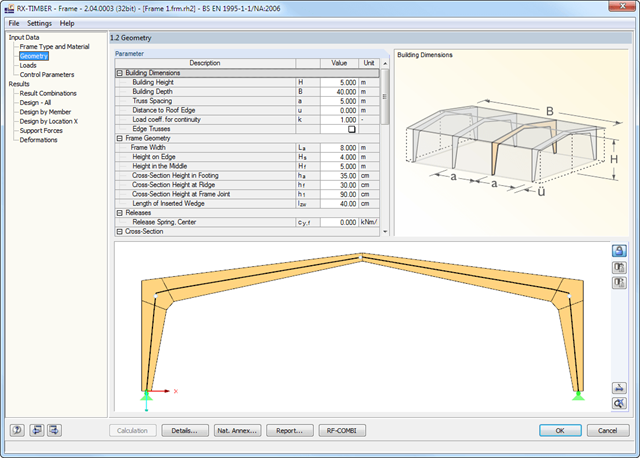
There are various options available for frame modeling. Graphical representations facilitate the geometry input. Modifications are updated automatically. Basic dimensions as well as geometrical data are entered in tables. During the input, the program checks the conditions required for the beam creation (for example, lamellas forming a curve) according to the defined standard. The most important geometry parameters are updated and displayed.
The relevant timber grade of the material can be selected from the material library. All material grades for glulam, hardwood, poplar and softwood timber specified in EN 1995-1-1 are available. Furthermore, it is possible to generate a strength class with user-defined material properties in order to extend the library. Permanent loads (for example, roof structure) can also be entered using the comprehensive and extensible material library.
Generators integrated in RX-TIMBER Purlin allow for convenient generation of various wind and snow load cases. By clicking the information buttons, the map of wind and snow zones for the relevant country is displayed. The corresponding zone can be selected with a double-click. Load cases can be checked graphically. However, you can enter load specifications manually as well. According to the generated loads, the program automatically creates combinations for the ultimate and serviceability limit states as well as for fire resistance design in the background. The generated combinations can be considered or adjusted by user-defined specifications.
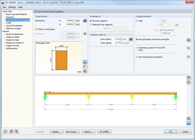
There are various options available for beam modeling. A roof type determines the exact purlin location for wind and snow generation.
Two beam types are available: continuous beam and purlin. If you select the continuous beam, it is possible to define several hinge conditions of the beam. If you select the purlin, it is not possible to modify hinge conditions. In this case, the calculation considers a double cross-section in the coupling zone. In addition, several coupling elements are available in the purlin settings:
- Nails (prebored/not prebored)
- Ring and plate connectors and bolts
- Screw connection with fastening system WT from SFS intec
- User-defined specification using characteristic strength
The relevant timber grade of the material can be selected from the material library. All material grades for glulam, hardwood and softwood timber specified in EC 5 are available. Furthermore, you have the option to generate a strength class with user-defined material properties and thus extend the library.A comprehensive and extensible material library can also be used for entering permanent loads (for example, roof structure).
Generators integrated in RX-TIMBER Purlin allow for convenient generation of various wind and snow load cases. By clicking the information buttons, the map of wind and snow zones for the relevant country is displayed. The corresponding zone can be selected with a double-click. Load cases can be checked graphically.
However, you can enter load specifications manually as well. According to the generated loads, the program automatically creates combinations for the ultimate and serviceability limit states as well as for fire resistance design in the background.