11 Wyniki
Wyświetl wyniki:
Sortuj według:
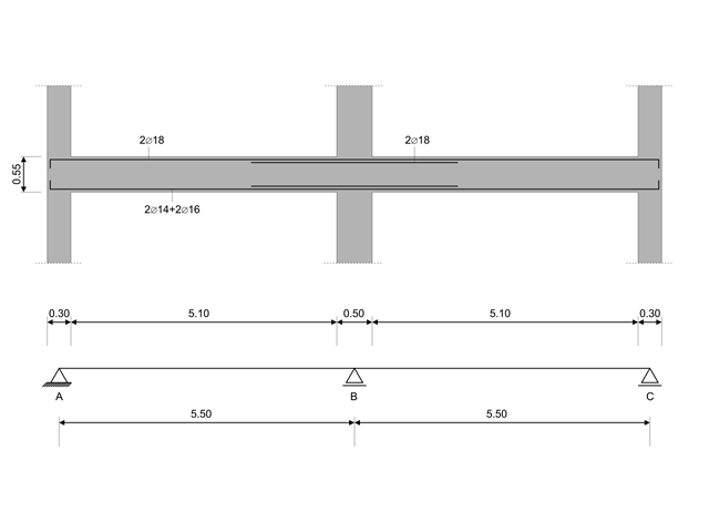
W tym przykładzie obliczeniowym obliczane są wartości nośności sił tnących na belkach zgodnie z EN 1998-1, 5.4.2.2 i 5.5.2.1 oraz nośność słupów przy zginaniu zgodnie z 5.2.3.3(2 ). System składa się z dwuprzęsłowej belki żelbetowej o rozpiętości 5,50 m. Belka jest częścią układu ramowego. Otrzymane wyniki są porównywane z wynikami w [1].
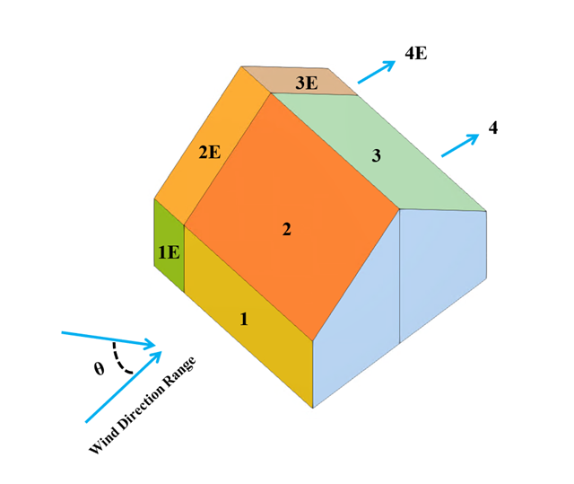
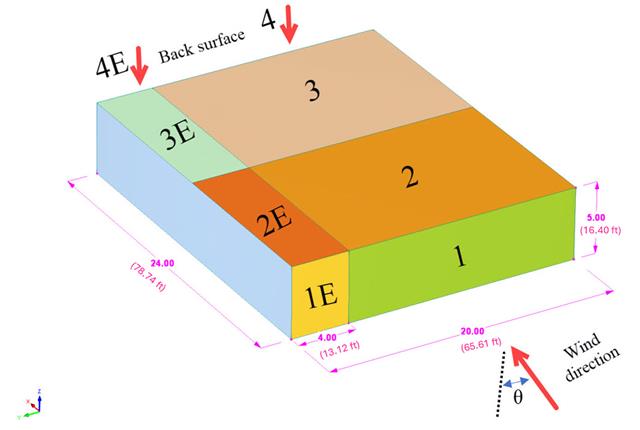
W bieżącym przykładzie walidacyjnym badany jest współczynnik ciśnienia wiatru (Cp) zarówno dla głównych elementów konstrukcyjnych (Cp,ave ), jak i drugorzędnych elementów konstrukcyjnych, takich jak systemy okładziny lub fasady (Cp,local ) w oparciu o NBC 2020 [1] and Baza danych japońskich tuneli aerodynamicznych dla niskiego budynku o nachyleniu 45 stopni. Zalecane ustawienie dla trójwymiarowego dachu płaskiego z ostrym okapem zostanie opisane w następnej części.
W poniższym przykładzie sprawdzamy wartość ciśnienia wiatru zarówno dla ogólnego projektowania konstrukcyjnego (Cp,10 ), jak i lokalnego projektowania konstrukcyjnego, takiego jak okładziny lub fasady (Cp,1 ) w oparciu o EN 1991-1-4, przykład dachu płaskiego [1] and Baza danych japońskich tuneli aerodynamicznych . Zalecane ustawienie dla trójwymiarowego dachu płaskiego z ostrym okapem zostanie opisane w następnej części.
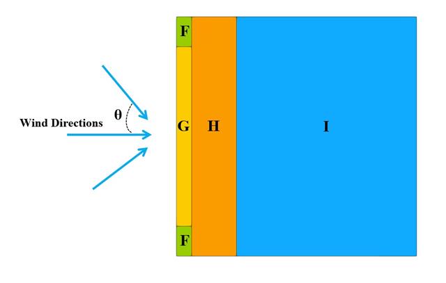
W bieżącym przykładzie walidacyjnym badamy współczynnik parcia wiatru (Cp) płaskiego dachu i ścian za pomocą ASCE7-22 [1]. W rozdziale 28.3 (Obciążenia wiatrem - główny układ odporności na siłę wiatru) i na Rysunku 28.3-1 (przypadek obciążenia 1) znajduje się tabela przedstawiająca wartość Cp dla różnych kątów nachylenia dachu.
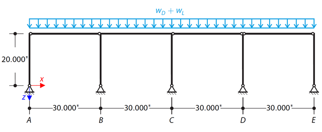
Za pomocą LRFD i ASD należy określić wymagane wytrzymałości i współczynniki długości efektywnej dla słupów z materiału ASTM A992 w ramie skręcania pokazanej na rysunku 1 dla maksymalnej kombinacji obciążeń grawitacyjnych.
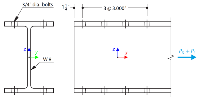
Wybrano pręt w kształcie litery W zgodny z ASTM A992 tak, aby przeniósł ciężar własny 30 000 kN i obciążenie rozciągające 90 000 kN. Sprawdź wytrzymałość pręta za pomocą LRFD i ASD.
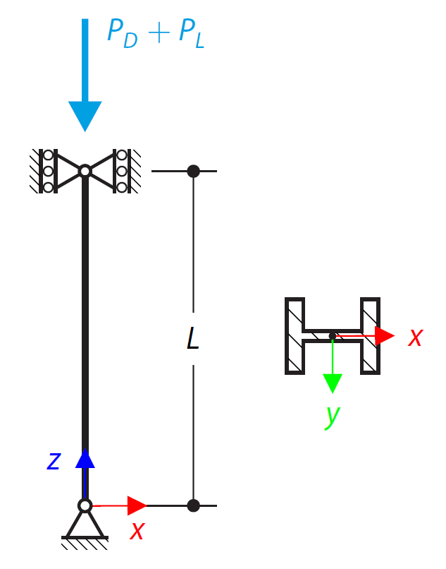
Słup w kształcie litery W zgodny z normą ASTM A992 14x132 jest obciążony zadanymi osiowymi siłami ściskającymi. Słup jest przegubowy na górze i na dole w obu osiach. Należy określić, czy słup jest w stanie wytrzymać obciążenie pokazane na rysunku 1 na podstawie LRFD i ASD.
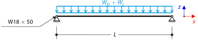
Rozważ belkę ASTM A992 W 18x50 dla stałych i równomiernych obciążeń stałych i ruchomych, jak pokazano na Rysunku 1. Pręt jest ograniczony do maksymalnej nominalnej głębokości wynoszącej 18 cali. Ugięcie pod obciążeniem użytkowym jest ograniczone do L/360. Belka jest swobodnie podparta i usztywniona. Sprawdź dostępną wytrzymałość na zginanie wybranej belki na podstawie LRFD i ASD.
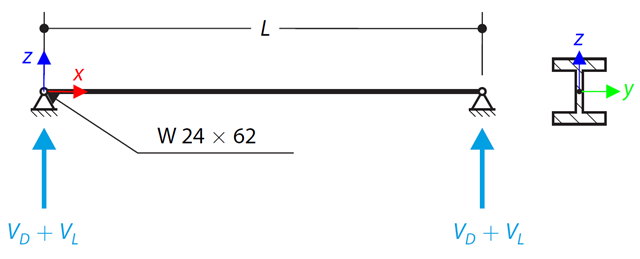
Na rysunku 1 pokazano belkę ASTM A992 W 24x62 o skróceniu do ścinania na końcu 48 000 i 145 000 kips od obciążeń stałych i użytkowych, odpowiednio Sprawdź dostępną wytrzymałość na ścinanie wybranej belki na podstawie LRFD i ASD.
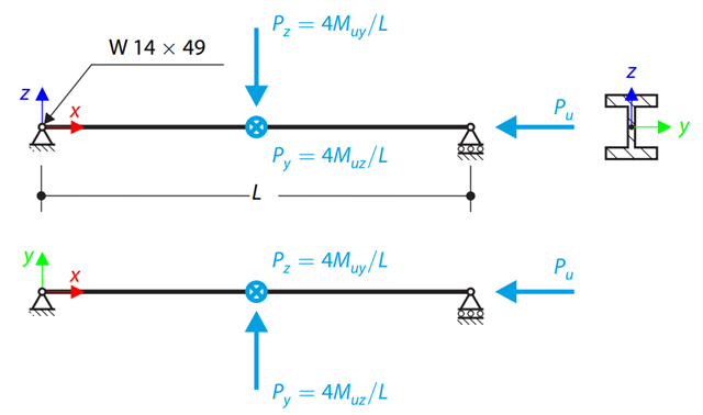
Korzystając z tabel ręcznych AISC, należy określić dostępne wytrzymałości na ściskanie i zginanie oraz czy belka ASTM A992 W14x99 ma wystarczającą wytrzymałość, aby przenieść siły osiowe i momenty pokazane na rysunku 1, uzyskane w analizie drugiego rzędu z uwzględnieniem efektów P-𝛿.