9 Wyniki
Wyświetl wyniki:
Sortuj według:
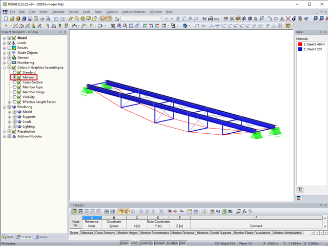
In RFEM und RSTAB können im Draht- und Vollmodell die verwendeten Materialien für Stäbe visuell über Farben überprüft beziehungsweise dargestellt werden.
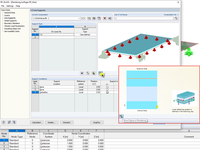
Im Zusatzmodul RF-GLAS ist zur Erleichterung der Definition der Auflagerbedingungen das 3D-Rendering implementiert. Ta interaktywna wizualizacja graficzna ułatwia wprowadzanie danych oraz kontrolę podpór liniowych i węzłowych. Die schematische Darstellung kann bei Bedarf jedoch auch ausgewählt werden.
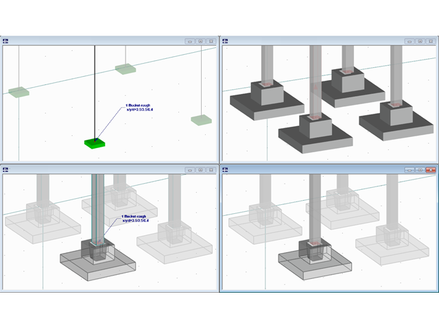
In RFEM und RSTAB stehen verschiedene grafische Darstellungen der Fundamentabmessungen zur Verfügung.
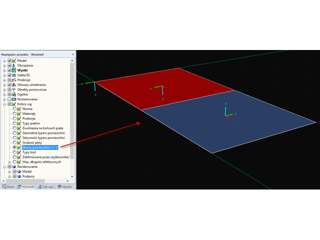
Über die entsprechende Option im "Zeigen-Navigator" können die Flächen im Rendering nach der Richtung der lokalen z-Achse eingefärbt werden. Standardmäßig werden die Seite, die in negativer z-Richtung liegt, rot und die diejenige, die in positiver z-Richtung liegt, blau eingefärbt.
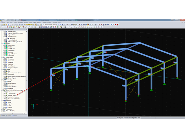
In RFEM und RSTAB können nun die verwendeten Stabtypen auch visuell über Farben überprüft beziehungsweise dargestellt werden. Dazu wurde eine Möglichkeit in den "Zeigen"-Navigator integriert.
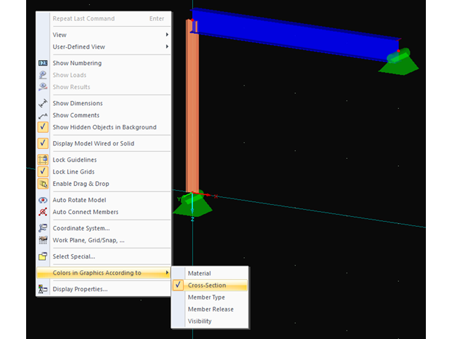
Zur übersichtlicheren Darstellung der Struktur ist es möglich, diese in verschiedenen Farben darzustellen. Die entsprechende Auswahl kann über einen Klick mit der rechten Maustaste in das Arbeitsfenster aufgerufen werden.
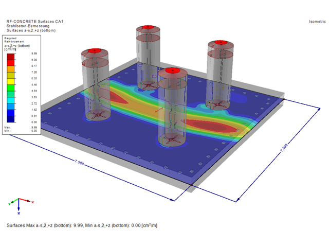
W programach RFEM 5 i RSTAB 8 można wymiarować fundamenty zgodnie z EN 1992-1-1 i EN 1997-1 w module dodatkowym RF-/FOUNDATION Pro.
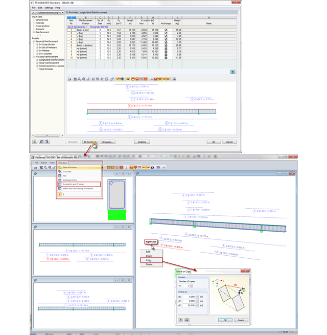
W modułach CONCRETE i RF‑CONCRETE Members można otworzyć okno dialogowe z renderingiem 3D istniejącego zbrojenia w oknie 3.1 lub 3.2. Dort ist es nun auch möglich, unterschiedliche Bewehrungsansichten in mehreren Dialogfenstern gleichzeitig anzeigen zu lassen. Die aus RFEM bekannte Auswahl "Isometrie mit 3 Ansichten" steht auch hier zur Verfügung.
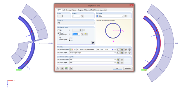
Podczas modelowania prętów w kształcie łuku może wystąpić problem pokazany na rysunku. Es scheint, als ob sich der Querschnitt des Stabes verdrillt beziehungsweise eine aufgebrachte Last bezogen auf die lokale z-Achse die Richtung ändert. Jak mogło do tego dojść?