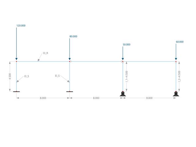
V tomto příkladu porovnáváme vzpěrné délky a součinitel kritického zatížení, které lze vypočítat v programu RFEM 6 pomocí addonu Stabilita konstrukce, s ručním výpočtem. Konstrukční systém je tuhý rám se dvěma přídavnými kloubovými sloupy. Tento sloup je zatížen svislými osamělými zatíženími.
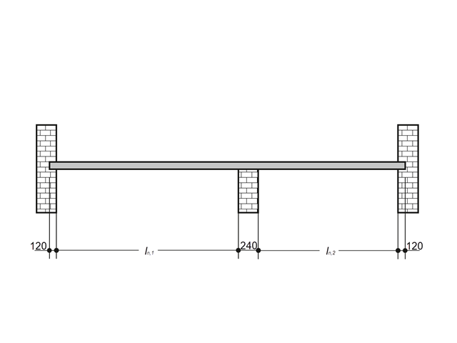
Železobetonová deska uvnitř budovy se má navrhnout jako pás o 1,0 m s pruty. Jedná se o jednosměrně pnutou podlahovou desku přes dvě pole. Deska je upevněna volně otočnými podpěrami na zděných stěnách. Střední podpěra má šířku 240 mm, zatímco šířka obou krajních podpěr je 120 mm. Na obě pole působí užitné zatížení kategorie C: obecní prostory.
Válec z pružně plastické zeminy se podrobí tříosým zkušebním podmínkám. Cílem je stanovit mezní svislé napětí pro porušení smykovým napětím při zanedbání vlastní tíhy. Uvažuje se počáteční hydrostatické napětí 100 kPa.
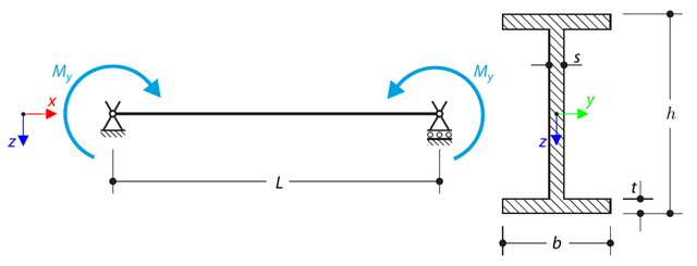
A simply supported beam is loaded by pure bending. Stanovíme kritické zatížení a příslušný součinitel zatížení od boulení.
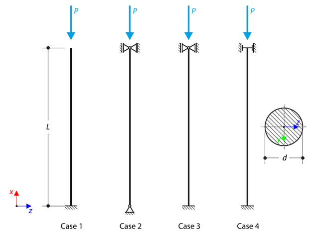
Dialog s kruhovým průřezem je podepřen podle čtyř základních případů Eulerova vzpěru a vystaven tlakové síle. Determine the critical load.
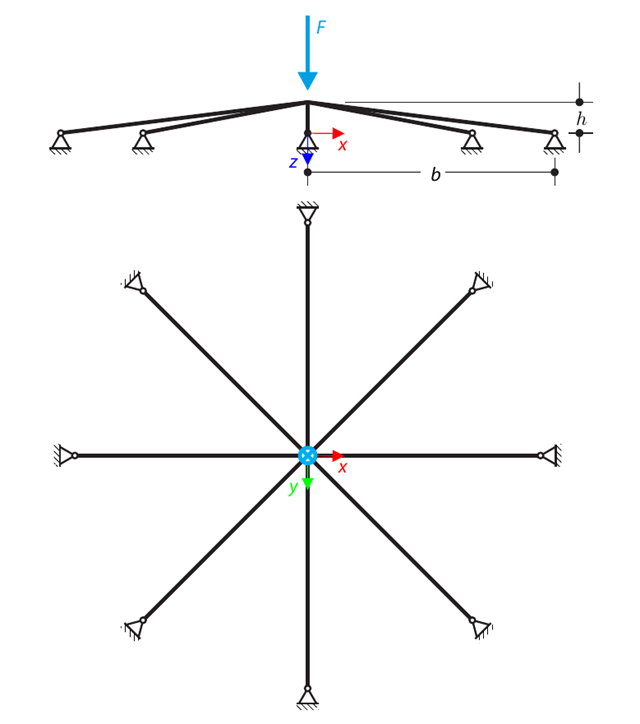
A symmetrical shallow structure is made of eight equal truss members, which are embedded into hinge supports. The structure is loaded by a concentrated force and alternatively by imposed nodal deformation over the critical limit point when the snap-through occurs. Imposed nodal deformation is used in RFEM 5 and RSTAB 8 to obtain the full equilibrium path of the snap-through. Vlastní tíha se v tomto příkladu nezohledňuje. Determine the relationship between the actual loading force and the deflection, considering large deformation analysis. Evaluate the load factor at the given deflections.
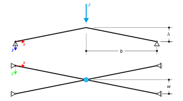
Konstrukce se skládá ze čtyř prutů, které jsou uloženy na kloubových podporách. The structure is loaded by a concentrated force and alternatively by imposed nodal deformation over the critical limit point, when snap-through occurs. Imposed nodal deformation is used in RFEM 5 and RSTAB 8 to obtain the full equilibrium path of the snap-through. The self-weight is neglected in this example. Determine the relationship between the actual loading force and the deflection, considering large deformation analysis. Evaluate the load factor at given deflections.
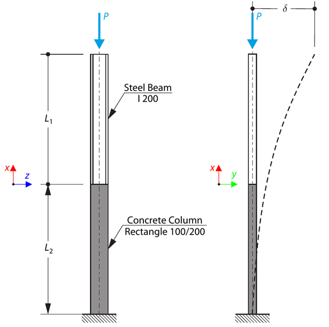
A column is composed of a concrete section (rectangle 100/200) and a steel section (profile I 200). Je vystaven tlakové síle. Determine the critical load and corresponding load factor. The theoretical solution is based on the buckling of a simple beam. In this case, two regions have to be taken into account due to different moments of inertia and material properties.
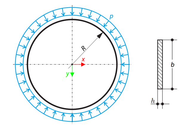
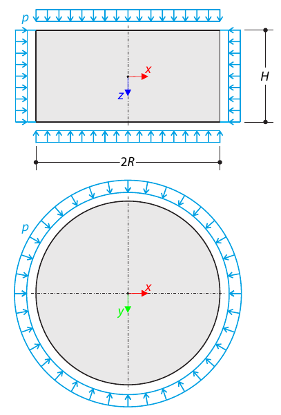
A thin circular ring of a rectangular cross-section is exposed to external pressure. Stanovíme kritické zatížení a příslušný součinitel zatížení pro vzpěr v rovině.
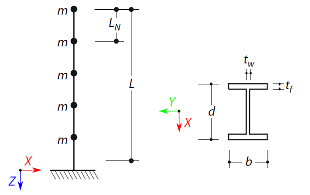
A cantilever beam with an I-beam cross-section of length L is defined. The beam has five mass points with masses m acting in the X-direction. Vlastní tíhu zanedbáme. The frequencies, mode shapes, and equivalent loads of this 5-DOF system are analytically calculated and compared with the results from RSTAB and RFEM.
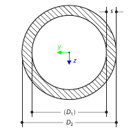
Analyticky stanovíme torzní konstantu pro průřez trubky (kruhovou oblast) a výsledky porovnáme s numerickým řešením v programech RFEM 5 a RSTAB 8 pro různé tloušťky stěn.
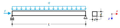
Ocelový nosník se čtvercovým průřezem je zatížen normálovou silou a spojitým zatížením. The image shows the calculation of the maximum bending deflection and critical load factor according to the second-order analysis.
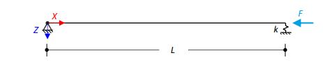
Osově zatížený ocelový nosník se čtvercovým průřezem je na jednom konci kloubově uložený a na druhém pružně podepřený. Two cases with different spring stiffnesses are considered. The verification example solves the calculation of the load factors of the beam in the image using the linear stability analysis.