In most cases, slender beams receive a parabolic shear stress in the web of the cross-section, which has the maximum value in the centroid of double-symmetric cross-sections.
According to DIN 18800, Part 3, Section 403, the following applies:
Shear stresses that are variable over the width b of the buckling panel should be considered with the larger of the following two values:
- Mean value of τ
- 0.5 max τ
In this case, the mean value of the shear stress is used for the buckling design.
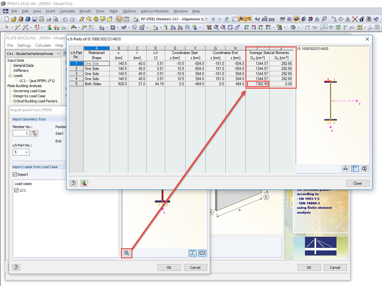
Since the variable shear stress τz depends on the statical moment Sy, there is a table with the details of the c/t-parts of the cross-section in PLATE‑BUCKLING. This also includes the average static moments, which in cases like this are used to determine the corresponding shear stresses for the buckling design according to the usual formula, but with the average static moment; see Formula and Image 01.
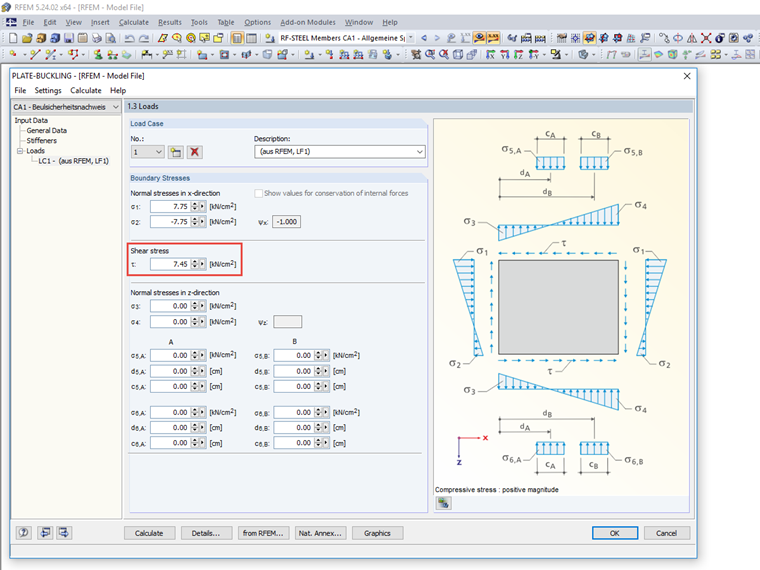
Accordingly, the following shear stress results in PLATE‑BUCKLING; see Image 02.
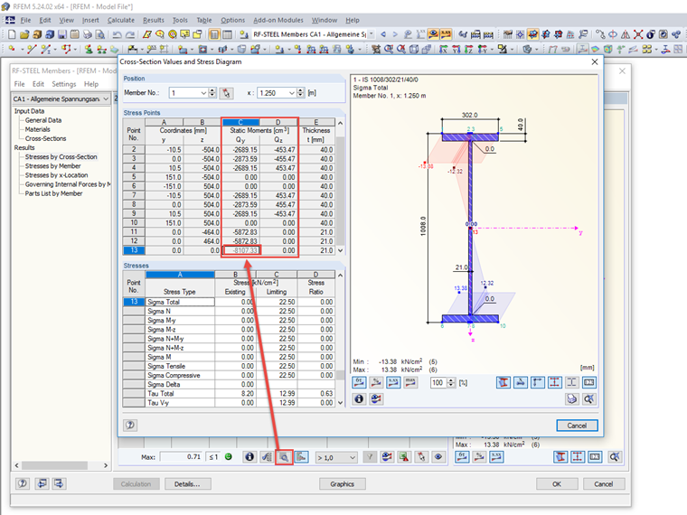
The respective static moments that are used to determine the shear stresses in RF‑/STEEL for the stress analysis can be displayed in the result window by clicking the "Show Cross-Section Values and Extended Stress Diagram" button; see Image 03.