Design of Tension Resistance According to EN 1993-1-1
According to DIN EN 1993‑1‑1, Chapter 6.2.3 (2), the tension resistance of a cross-section weakened by holes results from the minimum of the following design values:
|
Npl,Rd |
Bemessungswert der plastischen Zugbeanspruchbarkeit des Bruttoquerschnitts |
|
A |
Bruttoquerschnittsfläche |
|
fy |
Streckgrenze |
|
γM0 |
Teilsicherheitsbeiwert für Querschnittsbeanspruchbarkeit |
|
Nu,Rd |
Bemessungswert der Zugbeanspruchbarkeit des Nettoquerschnitts |
|
Anet |
Nettoquerschnittsfläche längs der kritischen Risslinie |
|
fu |
Zugfestigkeit |
|
γM2 |
Teilsicherheitsbeiwert für Querschnittsbeanspruchbarkeit bei Bruchversagen infolge Zug |
The net cross-section area is to be determined from the gross cross-section area minus all openings and holes for fasteners. Depending on the arrangement of the bolt holes, the hole deduction area to be applied is adjusted to the critical crack line.
Entering Data in RF-/STEEL EC3
By default, the design of the tension resistance in the add-on module is only performed considering the plastic tension resistance of the gross cross-section (Formula 1). The design according to Formula 2 can be activated by selecting the "Net Cross-Sectional Area" option in the "Parameters of Members" input window. You can enter a net cross-section area Anet for member start (x = 0) and member end (x = l). To enter the same net cross-section area for several members at the same time, we recommend using "Set input for member no."
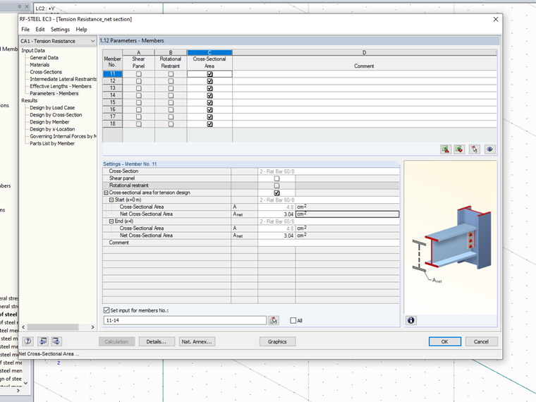
Then, both design values of the tension resistance are calculated and the design is performed according to DIN EN 1993‑1‑1 with the minimum value.
Modification for Design of Angle Sections Connected on One Side
For asymmetrically connected components, such as angle sections connected on one side to a leg, DIN EN 1993‑1‑8 provides additional regulations. Accordingly, the angle connected on one side for tensile loading may be designed like a centrally loaded angle if the load-bearing capacity is determined with an effective net cross-section.
|
Nu,Rd |
Bemessungswert der Zugbeanspruchbarkeit des Nettoquerschnitts |
|
Anet,eff |
Effektive Nettoquerschnittsfläche |
|
fu |
Zugfestigkeit |
|
γM2 |
Teilsicherheitsbeiwert für Querschnittsbeanspruchbarkeit bei Bruchversagen infolge Zug |
The effective net cross-section can be determined by means of modification factors depending on the number of bolts and the hole spacings. An additional reduction factor of 0.9, as in Equation 1, is no longer required for the design with the net cross-section. The input window in RF‑/STEEL EC3 does not allow you to enter the effective net cross-section directly, but the net cross-section area to be entered can be adjusted to the design in the add-on module by means of a simple conversion.
Design with Effective Net Cross-Section in Add-on Module
|
Nu,Rd |
Bemessungswert der Zugbeanspruchbarkeit des Nettoquerschnitts |
|
Anet,eff |
Effektive Nettoquerschnittsfläche |
|
Anet* |
Ersatznettoquerschnittsfläche für Eingabe in RF-/STAHL EC3 |
|
fu |
Zugfestigkeit |
|
γM2 |
Teilsicherheitsbeiwert für Querschnittsbeanspruchbarkeit bei Bruchversagen infolge Zug |
Example
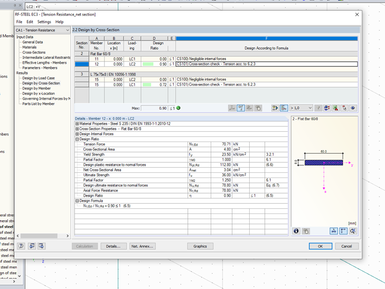
Flat bars 60 x 8 mm were selected as crossings in the Y-direction. The net area results for the fastening with an M20 screw in the critical crack line
|
Anet |
Nettoquerschnittsfläche längs der kritischen Risslinie |
|
A |
Bruttoquerschnittsfläche |
|
d0 |
Schraubenlochdurchmesser |
|
t |
Blechdicke |
Anet = 4.8 cm² - 2.2 cm × 0.8 cm = 3.04 cm²
The following design resistances result for the S235 material:
Npl,Rd = (4.8 cm² ⋅ 23.5 kN/cm²) / 1.0 = 112.8 kN
Nu,Rd = (0.9 × 3.04 cm² × 36 kN/cm²) / 1.25 = 78.8 kN
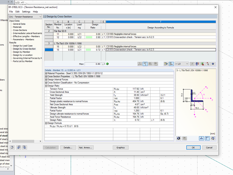
For the crossing in the X-direction, isosceles angle sections L 75 x 8 were selected in S355. The connection is to be realized on an angle leg with two M20 screws, one behind the other. The dimensions are selected as follows:
e1 = 40 mm
p1 = 60 mm
e2 = 30 mm
The effective net cross-section area for this connection situation results from the factor β2 according to EN 1993‑1‑8
β2 = 0.44
Anet,eff = β2 ⋅ Anet = 0.44 ⋅ (11.4 cm² - 2.2 cm ⋅ 0.8 cm) = 4.21 cm²
The following design resistances result for the S355 material:
Npl,Rd = (11.4 cm² × 35.5 kN/cm²) / 1.0 = 404.7 kN
Nu,Rd = (4.21 cm² ⋅ 49 kN/cm²) / 1.25 = 164.9 kN
The input in RF‑STEEL EC3 is carried out with the equivalent net cross-section area:
Anet* = 4.21 cm² / 0.9 = 4.67 cm²