


Design Background
To perform the design, it is necessary to create the relevant analytical model and verify it with regard to the standard or the general technical approval [3] of the individual products.
Verification of Analytical Model
First, the quality of the results on a drilling hole has to be checked. For this, it is important to define the FE mesh settings or to refine the FE mesh in the drilling area in such a way that the results correspond with the required values specified in DIN 18008.
The base structure is a rectangular plate with drilling:
a = 300 mm
b = 600 mm
t = 10 mm
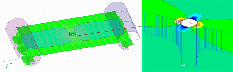
The result is the stresses of a maximum of 48.2 N/mm². They are within the allowable limit of 46 to 52 N/mm² in compliance with the approval [3], and thus the model can be used.
In addition to checking the stresses on a drilling hole, it is necessary to check the fitting modeling in the next step.
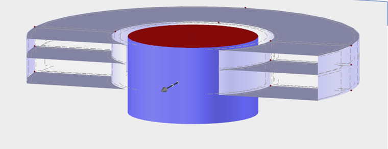
The surfaces of the top and bottom side of the fitting is modeled using contact solids, which can only transfer compression forces. The stiffness of the solid is selected according to the stiffness of the existing glass fitting.
For example, there are the following result values:
Material top side: E = 40 N/mm², G = 13.8 N/mm²
Material bottom side: E = 50 N/mm², G = 24.1 N/mm²
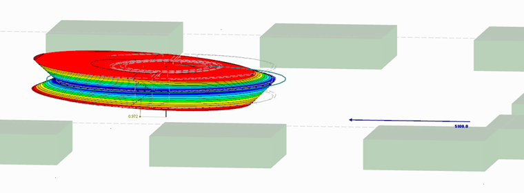
By applying the maximum allowable load limits FD/Z = 8,900 N and FQ = 5,100 N [3], the following stiffnesses result:
Compression Z / wZ = 19,347 N/mm
Tension D / wD = 20,602 N/mm
Shear Q / uQ = 5,247 N/mm
When comparing the values with the approval [3], all the results are within the allowable limits:
15,386 N/mm ≤ cZ,D ≤ 24,372 N/mm
344 N/mm ≤ cQ
Therefore, the model can be further used for the calculation.
The last step is the verification of the entire model. For this, both substructures modeled previously are merged. The considered structural dimensions as well as the required results refer to the technical approvals [3].
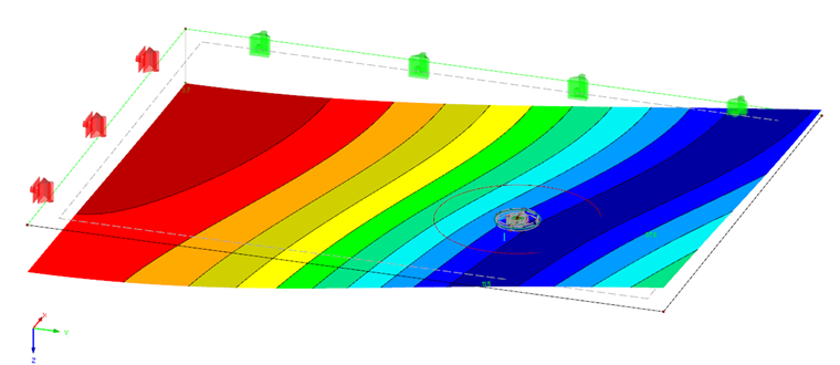
The results displayed in Figure 04 show very good congruity between the existing and the required results. This verified FE model is further used to as a basis for the calculation of the actual structural system.
Design Using FEM Analysis
As the structure with loads to be designed, the structural system described in Part 1 of the article will be used. Thus, the differences between both design types become clear.
The FEM model created previously will now be inserted into the structure to be designed. The resulting stresses are used for the design.
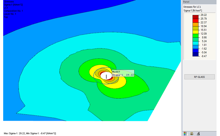
The maximum value of stresses in the drilling hole area is σ = 29.22 N/mm². Hence, the design ratio is η = 29.2 / 51.3 = 0.57.
Conclusion
A comparison of the two calculation methods clearly shows that there may be certain differences between the calculated design ratios. In the present case, the design ratio is about 40% lower due to the exact analysis. Although this cannot be generally assumed, it illustrates that a precise FEM analysis can often have advantages.