


Looking at the broken cross-section, this situation seems plausible and close to the reality. However, there are still several challenges when simulating this failure matter in an FE analysis environment. RFEM is ready to handle such tasks, providing nonlinear release elements for the implementation of the failure location by using various load levels.
Release Elements
The program environment of RFEM provides nodal, line, and surface releases under Model Data. A release in the model always describes the properties between two groups of structural components at the selected contact point. The properties between the component groups can be defined with regard to the setting of a member end release for each direction of degrees of freedom (x, y, z, φx, φy, φz). In addition to a complete release of the direction up to a nonlinear deformation behavior, the releases provide a wide range of options for defining the properties.
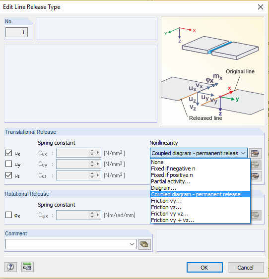
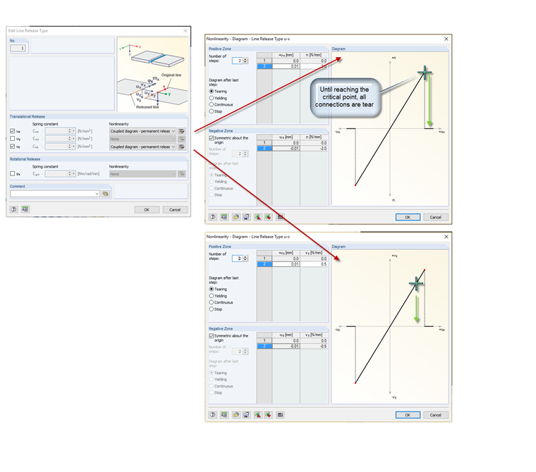
In general, all options except the nonlinearity setting "Coupled diagram - permanent release" only respond in the assigned direction. In the case of the coupled release, the degrees of freedom can be linked together. The linkage of the degrees of freedom refers to the "Tearing" failure condition of the respective work diagram. If the deformation reaches the failure point of the assigned diagram at the respective contact side in a specific direction, the connection in the actual direction as well as in all other directions with the "Coupled diagram - permanent release" setting also fails at this location. In the case of the coupled failure, the degrees of freedom in the x- and y-directions apply the failure point in the first and third quadrants of the diagram, and the z-direction applies the failure point in the first quadrant.
The release elements display no coupling forces. The force transfer results from the discontinuity between the adjacent elements.
Application
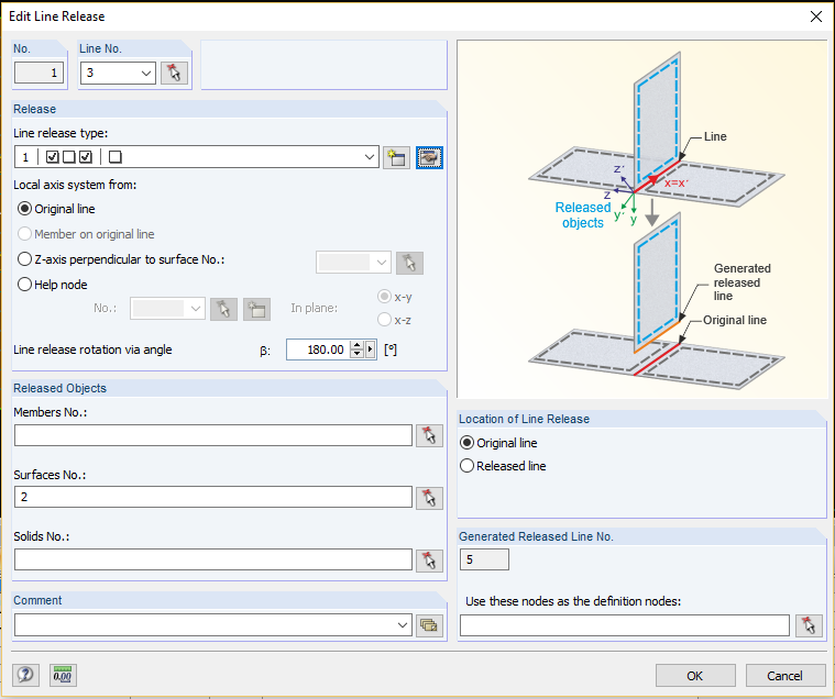
Open the release elements using the menu "Insert" -> "Model Data" -> "Nodal, Line, Surface release". After specifying the contact point (Node, Line, or Surface No.), contact property (Release Type), and which elements belong to the adjacent group (Released Objects), the elements can be transferred to the model. The program then copies the contact point in the background and assigns this generated definition to the selected adjacent elements (released elements). The elements on the other adjacent side remain as they are. The defined contact property is determined between the originally defined contact point and the copied contact point.
With this function, RFEM opens up a completely new field of application: In the midst of supporting structures consisting of members, shells, and solids, it is possible to simulate discrete connections such as cracks, pressure contact, brittle joints, and so on.