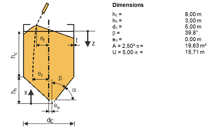
Layout and Dimensions
The structural system is shown in Image 01.
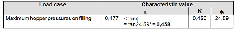
Governing characteristic values for different load applications
The applicable extreme values of particulate solids for the maximum hopper pressures in the full condition are included in the following table.
Physical properties
The loads on the walls of silo hoppers should be determined according to EN 1991‑4 [1], 6.1.1(2) with regard to the steepness of the hopper walls in compliance with the following classes:
The hopper is classified as a shallow hopper.
Filling Loads
Janssen characteristic depth zo
Vertical distance ho
For a symmetrically filled circular silo, the vertical distance ho between the equivalent surface of the solid and the highest solid‑wall contact is calculated as follows:
Parameter n
Coordinate z
z = hc = 8.00 m 6.1.2(2)
Vertical pressure pvf
Bottom load magnifier Cb
Cb = 1.0 (6.3)
The bottom load magnifying factor Cb applies to silos of Action Assessment Class 2 under the condition that the stored solids do not tend to dynamic behavior.
Mean vertical pressure at the hopper transition
pvtf = Cb · pvf (6.2)
pvtf = 1.0 · 69.27 = 69.27 kN/m2
Mobilized friction
In a shallow hopper, the waIl friction is not fully mobilized. The mobilized or effective wall friction coefficient should be determined as:
Parameter n
n = S · (1 - b) · μheff · cot β (6.28)
S = 2 (6.9)
n = 2 · (1 - 0.2) · 0.33 · cot 39.8° = 0.634
Parameter Ff
Parameter n
n = S · (Ff · μheff · cot β + F) - 2 (6.8)
n = 2 · (0.943 · 0.33 · cot 39.8° + 0.943) - 2 = 0.634
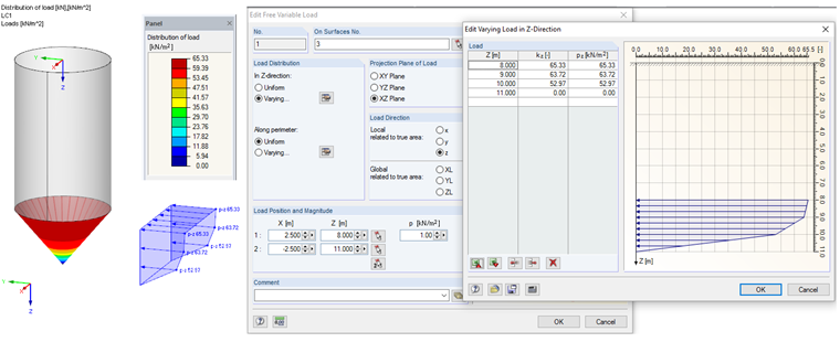
Loads perpendicular to hopper walls
pnf(x) = Ff · pv(x) (6.29)
pnf(0.00) = 0.00 kN/m²
pnf(1.00) = 52.97 kN/m²
pnf(2.00) = 63.72 kN/m²
pnf(3.00) = 65.33 kN/m2
This load can be entered in RFEM as a free variable load. The load input is displayed in Image 03.
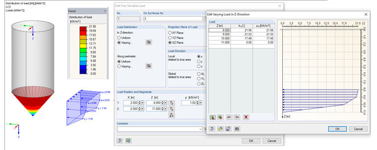
Hopper frictional traction
ptf(x) = μheff · Ff · pv(x) (6.30)
ptf(0.00) = 0.00 kN/m²
ptf(1.00) = 0.33 · 52.97 = 17.48 kN/m2
ptf(2.00) = 0.33 · 63.72 = 21.03 kN/m2
ptf(3.00) = 0.33 · 65.33 = 21.56 kN/m2
This load can be entered in RFEM as a free variable load. The load input is displayed in Image 04.