


Methods for Calculating Deformation / Deflection
C1: Analytical Calculation – Member
The calculation method according to EN 1992‑1‑1, Section 7.4.3 [1], allows for a simplified approximation of the deformation in the cracked state. Using this method, the deformation is determined on an extracted member structure. The connected structural elements such as surfaces, for example, are not considered in the calculation.
C2: Analytical Calculation – Surface
The RF-CONCRETE Deflect add-on module determines the deformations in the cracked state using a method based on the analytical calculation method according to EN 1992‑1‑1, Section 7.4.3. In this case, linear-elastic material properties are applied to the reinforcing steel and concrete until the tension strength is reached. If the tension strength of the concrete is exceeded, damage development occurs. The analyzed structure must consist entirely of surfaces. This calculation method is suitable for surfaces subjected to bending.
C3: Nonlinear Calculation – Member
This is a physically nonlinear method that considers crack formation and the accompanying redistribution of internal forces in the deformation analysis. The analyzed structure must be a pure member structure.
C4: Nonlinear Calculation – Surface
This is a physically nonlinear method that considers crack formation and the accompanying redistribution of internal forces in the deformation analysis. The analyzed structure must consist entirely of surfaces. In this method, a two-dimensional surface model is internally expanded via the height. For this, the steel cross-section is divided into a defined number of steel and concrete layers (called "layers"). For further information, see the RF-CONCRETE Surfaces manual, Chapter 2.8.2 [1].
C5: Nonlinear Calculation – Combined Structure
In theory, structures consisting of both surfaces and members can be analyzed using the stiffness export. RF-CONCRETE Members and RF-CONCRETE Surfaces provide the option to export the stiffness determined in the cracked state to RFEM in a load case or a load combination. The calculation is started in one of the two modules, the stiffness is exported to RFEM, and the other module performs the nonlinear calculation once again to consider the exported stiffness. It should be noted that the interaction between the surface and the member element might not be considered in a single export of the stiffness.
Modeling Options
The available calculation methods can be combined with various modeling approaches in the modeling or they can be linked to them. This will be explained below, using an example of a simply supported beam with a T-section.
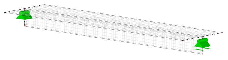
M1: Beam Structure
The structure is modeled as a pure member structure. A possible modeling option is to detach the individual components from the entire structure and analyze them separately, or to create the structure from members only.
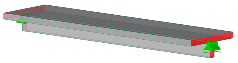
M2: Combined Structure of Member and Surface Elements
T-beam chords are modeled as a surface element and the web as a member element. This is a typical model when using members of the Rib type. The Rib member type can only be used for the analytical calculation (C1). For the nonlinear calculation method (C3), the rib must be converted into an eccentric beam member, since it has no actual stiffness in the model.
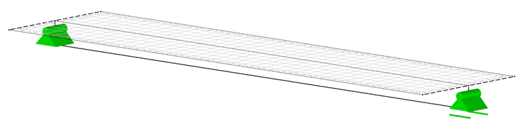
M3: Folded Plate Structure with Vertically Arranged Web
The structure is modeled as a pure folded plate structure without member elements. When modeling the structure as a surface model, you can attribute the cross-section of the T-beam to a structural line, which defines the position and the orientation of the surfaces. Thus, the web would be modeled as a vertical surface, which is orthogonal to the surfaces of the chord.
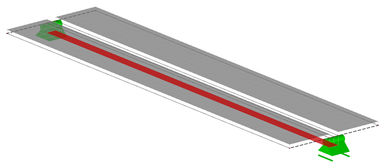
M4: Folded Plate Structure with Horizontally Arranged Web
As in the case of M3, the model consists entirely of surfaces. Both the chords and the web are modeled as a surface with eccentricity arranged horizontally to the centroidal axis. The surface forming the web has a thickness corresponding to the overall height of the structure.
General Information About Modeling in Add-on Modules
Basically, for a deformation calculation in the cracked state, an existing reinforcement should be defined in the systems that comes as close as possible to, or, in the best case, matches the actually designed reinforcement. In RF-CONCRETE Members, the existing reinforcement can be adjusted and saved as a template (see RF-CONCRETE Members, Chapter 3.6 [3]). In RF-CONCRETE Surfaces, you can define the amount of the existing reinforcement manually or for each element, surface by surface (see RF-CONCRETE Surfaces, Chapter 3.4.3 [2]).
Combination of Methods for Determining Deformation and Modeling
Depending on the modeling, only certain methods are suitable for the deformation analysis. The following table shows the possible combinations.
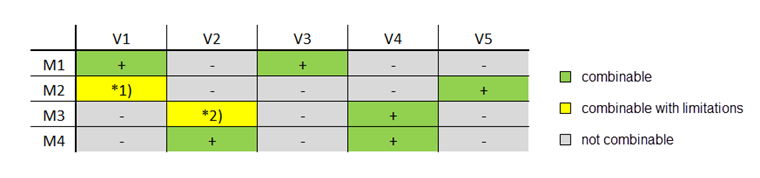
*1) If using a Rib member type in M2, it is possible to perform the analytical calculation C1. In the case of eccentric members, a part of the surface would be neglected when using C1.
*2) It should be noted that the C2 method is designed for structural components predominantly subjected to bending.