


Modeling Masonry Wall with Linear Material Model
Full Shear Coupling
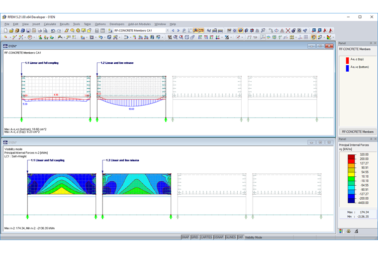
The downstand beam and the rib in the 3D model are supported by a force pair. For typical bending resistance, a compression component is created in the web and a compression component in the slab. If, in this context, the masonry wall above the downstand beam is connected to the floor with its full shear coupling, the entire structure acts together. That does not reflect the reality. There is the risk that the rib will be significantly underdesigned.

No Shear Coupling
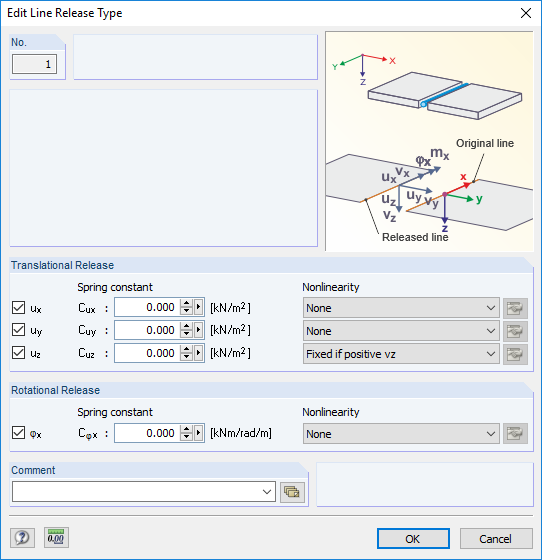
You can define a line release to prevent the rib and wall from acting together. You have to release the degree of freedom Cux. Furthermore, you should prevent the rib from hanging on the wall through the vertical component. The behavior can be represented by a nonlinearity (fixed if positive vz). This nonlinearity is also the reason to select a line release instead of a line hinge.
Compared to the full shear coupling, the downstand beam now has a much higher load. The reinforcement has almost quadrupled.
However, the question remains as to whether the distribution of internal forces in the wall is realistic, and whether there are any effects in this context that could have an effect on the loading of the rib.
Modeling Masonry Wall with Nonlinearity
Modeling with "Membrane Without Tension"
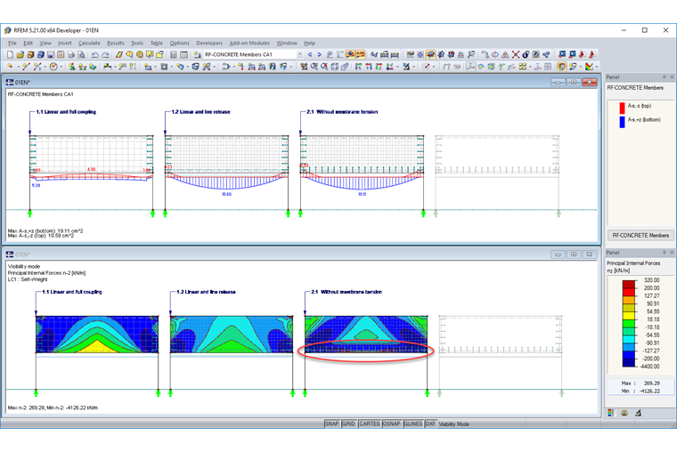
Another approach in this article is to display the masonry wall as a surface of the "Membrane Without Tension" type. It should be mentioned here that it is important to ensure that the wall cannot absorb tensile forces. During the subsequent rib design, you will determine approximately the same reinforcement results. When considering the axial forces, you can see the distribution of the compression struts in the wall. It is noticeable that there is a horizontal compression strut on the bottom side of the wall now.
Modeling with "Isotropic Masonry 2D" Material Model
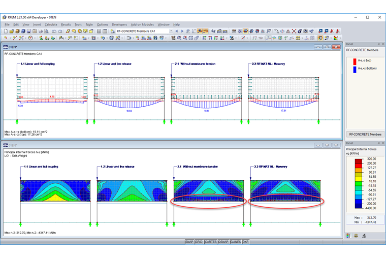
In order to check the model results with the "Membrane Without Tension" surface type, we will create another model using the "Isotropic Masonry 2D" material model. The material model is adjusted in such a way that the masonry cannot absorb any tensile force.
The two results are approximately identical. However, this model also has a horizontal compression strut at the bottom edge of the masonry wall.
Modeling While Considering Construction Progress
The construction progress may be affected, depending on when the downstand beam and the connected slab are stripped. If the slab is removed before the masonry wall above is constructed, no loading can occur in the story above or in the masonry wall due to the permanent loads of the bottom story. The masonry wall would not exist at this time. In order to check this correlation, it is necessary to carry out a calculation by taking the construction phases into account. Image 06 clearly shows that no compression strut is present at the bottom edge of the wall (see Image 05).
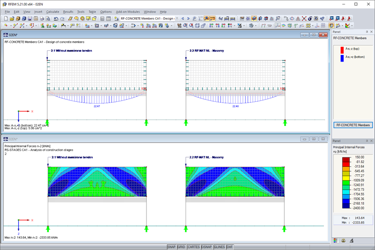
When designing the rib based on the internal forces determined while considering the construction phases, the result shows a reinforcement increase of about 20%.
Conclusion
When you display a masonry wall using a rib, you have to make sure that the wall takes no loads from the rib. You can ensure this in part by using line hinges and releases. Furthermore, you have to find out if the construction phases have an influence. It is important to avoid subjecting the masonry wall in the model to loading at a time when such loading does not yet exist.
