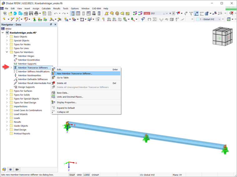
To define member transverse stiffeners, open the dialog box “New Member Transverse Stiffener”. This dialog box includes the main properties of each stiffener type (Image 2). First, you have to define the stiffener type. The following types are currently available: flat stiffeners, end plates at the start and end of the member, channel sections, angle profiles (connection of both legs to the stiffened web), connected columns at the start and end of the member, and warping restraints.
The position of the stiffeners can be defined with an absolute or a relative input, and you can easily switch between the two. Please note that the entered positions apply to all members to which the member transverse stiffeners are assigned. If the members have different lengths, the absolute and relative position specifications differ. Then, automatic conversion is not possible.
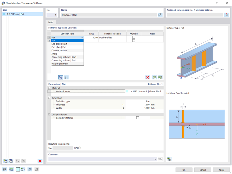
The "Multiple" check box allows you to add more stiffeners of the same type to a member (Image 3). You can specify the number of stiffeners and the offset in the Parameters section of the dialog box. In this section, information about the material and dimensions of the stiffener is required as well.
If you have activated a design add-on (for example, Steel design or Aluminum design), the check box “Consider stiffener” is also available here. By activating it, you can include the stiffener in the associated add-on. Hence, only member transverse stiffeners for which this check box is activated will be considered in the design.
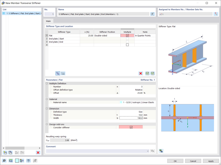
You can use member stiffeners to define the boundary conditions for warping when calculating members with 7 degrees of freedom. The warping is considered as a local member internal force; therefore, no further global support conditions have to be defined. In RFEM 6 and RSTAB 9, the resulting warp spring is automatically calculated for each transverse stiffener type and the given cross-section. Please note that the displayed resulting warp spring stiffness is strictly informative when using the member transverse stiffeners for design.
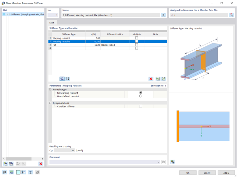
You can also define a full warping restraint or a user-defined warping restraint directly by using the "Warping restraint" stiffener type, as shown in Image 4.
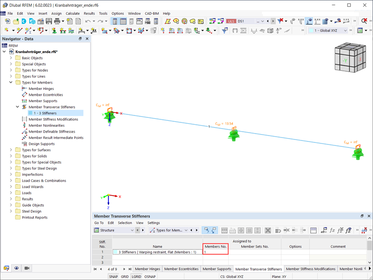
Finally, the member transverse stiffeners can be assigned to one or more members using the "Edit Member" dialog box, by selecting them in the "Member Transverse Stiffener" dialog box, or via the input table (Image 5). It is also possible to assign the member transverse stiffeners to a member set. In this case, the relative position of the stiffener types then refers to the length of the entire member set. Please note that the stiffener can be assigned either to a member or to the superordinate member set.