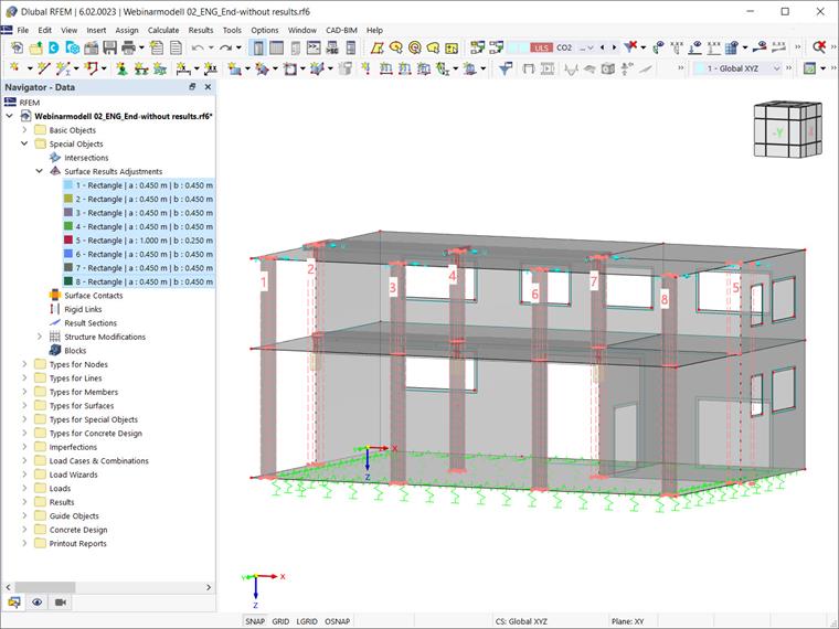
The above-mentioned function is available under "Special Objects" in the Data navigator. Its use will be shown by defining surface results adjustments for the connection zones between the columns and the slabs in Image 2. The goal is to define areas corresponding to the dimensions of the column and to set to zero the surface internal forces within the zone.
Although we are interested in defining the quadratic/rectangular area corresponding to the column dimensions (0.450x0.450m), the adjustment zone can also be defined in different forms, such as a circle or ellipse (Image 3). Depending on the selection, it is necessary to define the shape-specific parameters (for example, width, length, or diameter). If needed, you can rotate the zone by specifying the value of the “Angular rotation”.
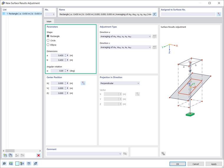
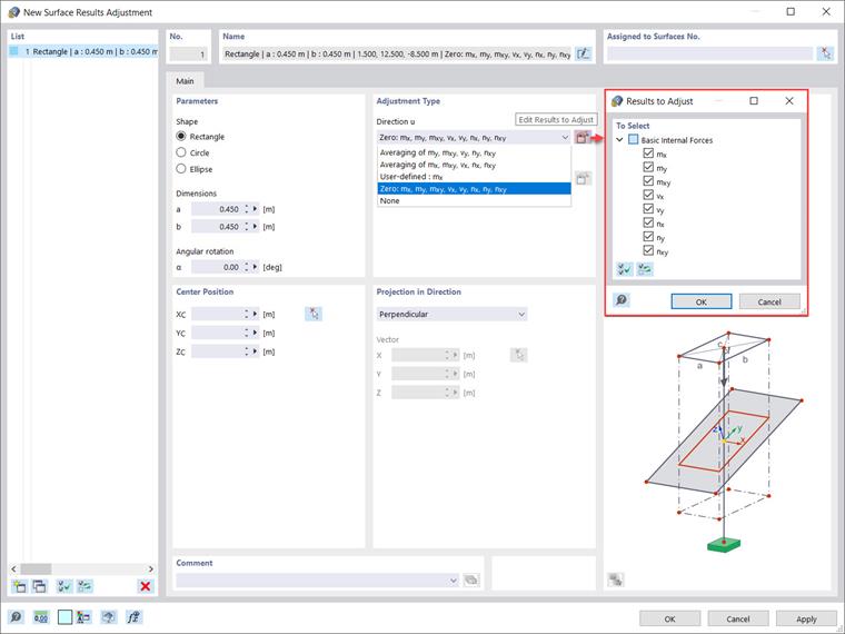
The next step is to define the adjustment type for the direction “u” as the first direction and “v” as orthogonal to it. Hence, you can define the surface internal forces and moments to be taken into account for smoothing. The following options are available: averaging of my, mxy, vy, ny, nxy; averaging of mx, mxy, vx, nx, nxy; user-defined, zero, or none. The first two represent the default settings for basic internal forces in surface directions y and x, respectively.
“User-defined” allows you to select the types of internal forces whose results should be averaged. “Zero” means that the results within the zone are set to zero, whereas “None” means that surface internal forces are not averaged, but displayed as usual. In this example, the results within the zone are set to zero and the types of internal forces to adjust are selected via the “Edit Results to Adjust” icon, as shown in Image 4.
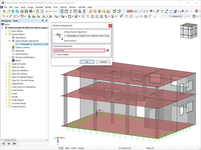
You can use the “Select Surfaces in Graphics” icon in the upper right corner to assign the surfaces for the surface results adjustment of interest. In this example, we want to have the surface results adjustment on all slabs; therefore, all the corresponding surfaces are selected (Image 5).
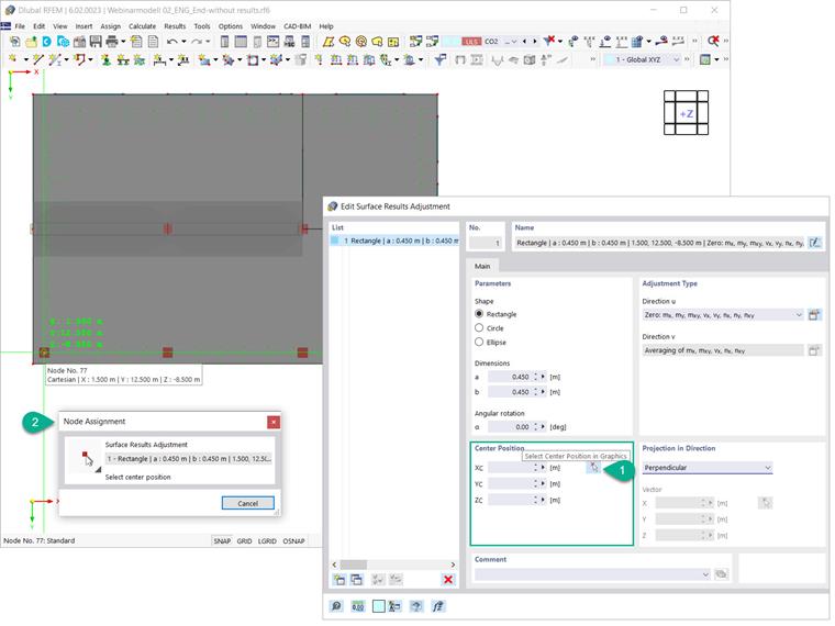
Next, you must specify the center of the adjustment zone. You can do this by entering coordinates directly in the “New Surface Results Adjustment” dialog box, or define them graphically as shown in Image 6.
Since all surface results adjustments will be assigned to the same surfaces, in the “Surface Results Adjustment” window you can create 6 copies of the initially created adjustment and just modify their individual center position.
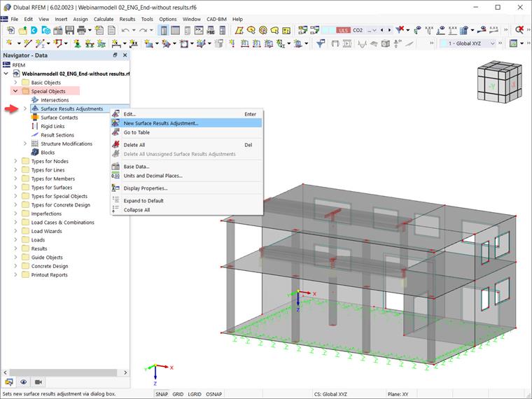
It is also possible to select the surface results adjustments in the RFEM working window and simply use the drag & drop function to define them as shown in Image 7. Please be aware that for the sake of completeness, a surface results adjustment associated with the walls must also be created. In this example, this is surface results adjustment No. 5 with dimensions of 1.000x0.250m.