.png?mw=960&hash=ef676d6ce95d12e3f6644fe80bfe725ee6232ac0)
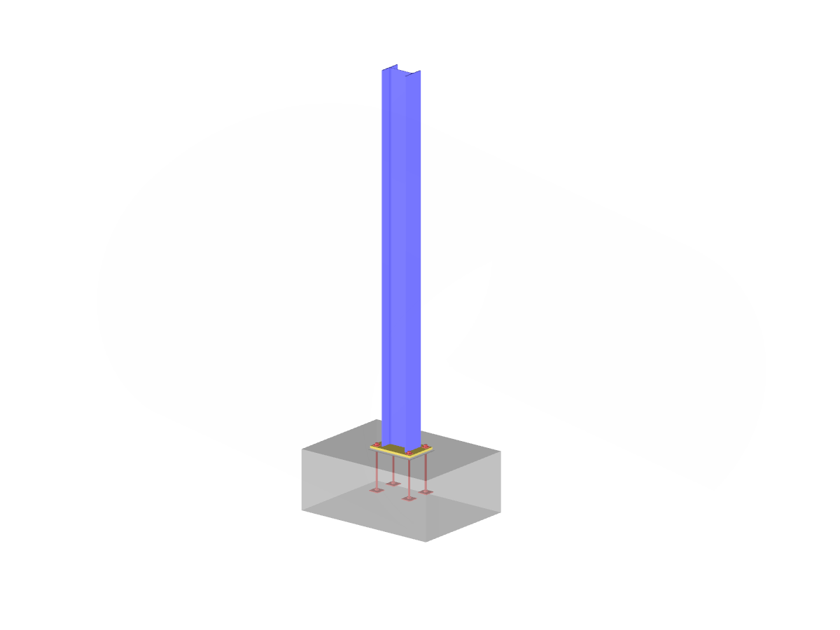
The model describes a frame with a structural eccentric base plate on the foundation. Direction parameters can be entered in Window 1.4 in RF-/JOINTS Steel – Column Base to precisely define the deviation from the center position. This setting allows for individual adjustments to foundation-related requirements. The image shows a technical display of the entire arrangement and highlights the design of the eccentric base plate.
Model Used in
Eccentrically Arranged Base Plate
| Number of Nodes | 3 |
| Number of Lines | 2 |
| Number of Members | 2 |
| Number of Load Cases | 1 |
| Total Weight | 1,248 t |
| Dimensions (Metric) | 6.313 x 0.313 x 4.313 m |
| Dimensions (Imperial) | 20.71 x 1.03 x 14.15 feet |
| Program Version | 5.25.00 |
You can download this structural model to use it for training purposes or for your projects. However, we do not assume any guarantee or liability for the accuracy or completeness of the model.
Related Models