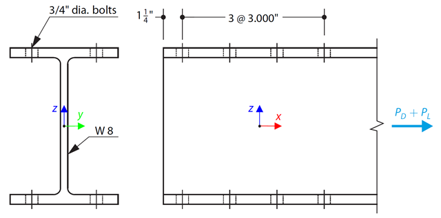
An ASTM A992 W-shaped member is selected to carry a dead load of 30.000 kips and a live load of 90.000 kips in tension. Verify the member strength using both LRFD and ASD.
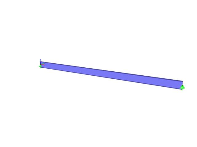
Consider an ASTM A992 W 18×50 beam forspan and uniform dead and live loads as shown in Figure 1. The member is limited to a maximum nominal depth of 18 inches. The live load deflection is limited to L/360. The beam is simply supported and continuously braced. Verify the available flexural strength of the selected beam, based on LRFD and ASD.

Consider an ASTM A992 W 18x50 beam forspan and uniform dead and live loads as shown in Figure 1. The member is limited to a maximum nominal depth of 18 inches. The live load deflection is limited to L/360. The beam is simply supported and continuously braced. Verify the available flexural strength of the selected beam, based on LRFD and ASD.
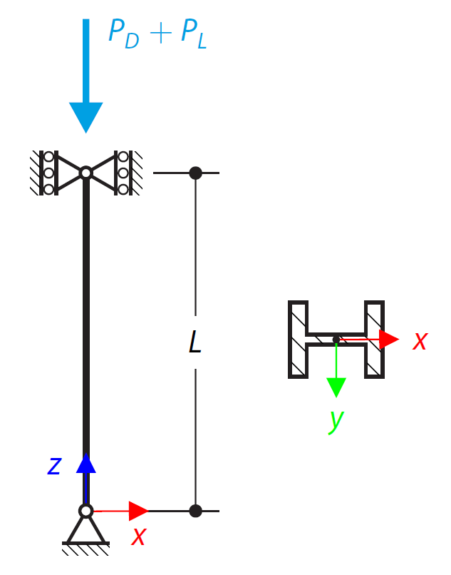
An ASTM A992 14×132 W-shaped column is loaded with the given axial compression forces. The column is pinned top and bottom in both axes. Determine whether the column is adequate to support the loading shown in Figure 1 based on LRFD and ASD.
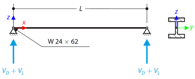
An ASTM A992 W 24×62 beam with end shears of 48.000 and 145.000 kips from the dead and live loads, respectively, is shown in Figure 1. Verify the available shear strength of the selected beam, based on LRFD and ASD.

An inner column in the first floor of a three-story building is designed. The column is monolithic connected with the top and bottom beams. The fire design simplified method A for columns according to EC2-1-2 is than proofed and the results compared to [1].

In this verification example, the capacity design values of shear forces on beams are calculated in accordance with EN 1998-1, 5.4.2.2 and 5.5.2.1 as well as the capacity design values of columns in flexure in accordance with 5.2.3.3(2). The system consists of a two span reinforced concrete beam with a span length of 5.50m. The beam is part of a frame system. The results obtained are compared with those in [1].

A reinforced concrete beam is designed as a two-span beam with a cantilever. The cross-section varies along the length of the cantilever (tapered cross-section). The internal forces, the required longitudinal and shear reinforcement for the ultimate limit state are calculated.

In this example, the shear at the interface between concrete cast at different times and the corresponding reinforcement are determined according to DIN EN 1992-1-1. The obtained results with RFEM 6 will be compared to the hand calculation below.
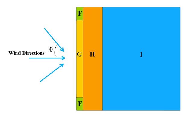
In the current validation example, we investigate wind pressure value for both general structural design (Cp,10) and local structural design such as cladding or façade systems (Cp,1) based on EN 1991-1-4 flat roof example [1] and Japanese Wind Tunnel Data Base . The recommended setting for three-dimensional flat roof with sharp eaves will be described in the next part.