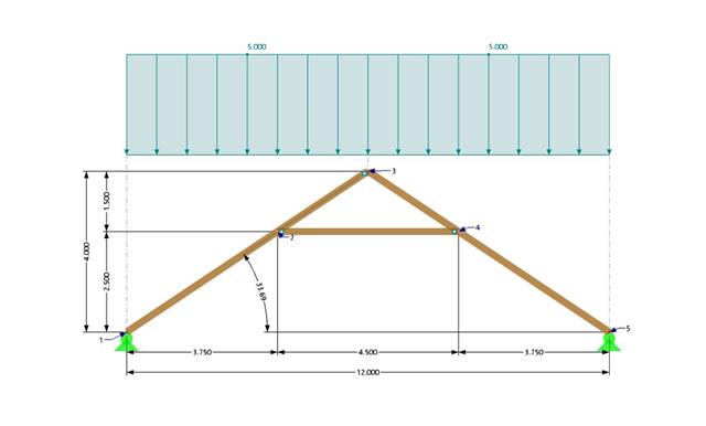
A collar beam roof with the selected geometry is compared in terms of its internal forces between the calculation using RFEM 6 and the manual calculation. In total, three load systems are analyzed.

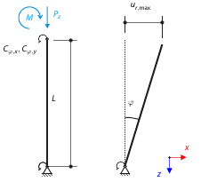
This example compares the effective lengths and critical load factor, which can be calculated in RFEM 6 using the Structure Stability add-on, with a manual calculation. The structural system is a rigid frame with two additional hinged columns. This column is loaded by vertical concentrated loads.

In this example, the shear at the interface between concrete cast at different times and the corresponding reinforcement are determined according to DIN EN 1992-1-1. The obtained results with RFEM 6 will be compared to the hand calculation below.

A reinforced concrete beam is designed as a two-span beam with a cantilever. The cross-section varies along the length of the cantilever (tapered cross-section). The internal forces, the required longitudinal and shear reinforcement for the ultimate limit state are calculated.

In this verification example, the capacity design values of shear forces on beams are calculated in accordance with EN 1998-1, 5.4.2.2 and 5.5.2.1 as well as the capacity design values of columns in flexure in accordance with 5.2.3.3(2). The system consists of a two span reinforced concrete beam with a span length of 5.50m. The beam is part of a frame system. The results obtained are compared with those in [1].

An inner column in the first floor of a three-story building is designed. The column is monolithic connected with the top and bottom beams. The fire design simplified method A for columns according to EC2-1-2 is than proofed and the results compared to [1].

In the current validation example, we investigate wind pressure value for both general structural designs (Cp,10) and cladding or façade design (Cp,1) of rectangular plan buildings with EN 1991-1-4 [1]. There are three dimensional cases that we will explain more about if in the next part.
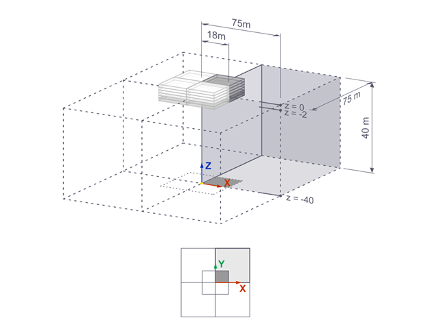
The settlements of a rigid square foundation on a lacustrine clay [1] are calculated with RFEM. One quarter of the foundation is modelled. The foundation has a width of 75.0 m in both sides. Construction stages are used to generate the results.
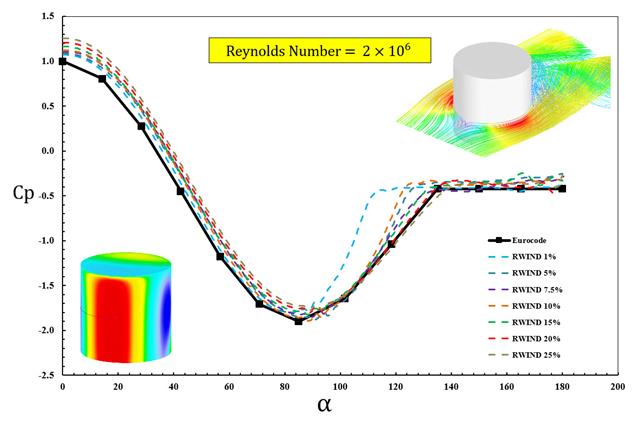
The available standards, such as EN 1991-1-4 [1], ASCE/SEI 7-16, and NBC 2015 presented wind load parameters such as wind pressure coefficient (Cp) for basic shapes. The important point is how to calculate wind load parameters faster and more accurately rather than working on time-consuming as well as sometimes complicated formulas in standards.
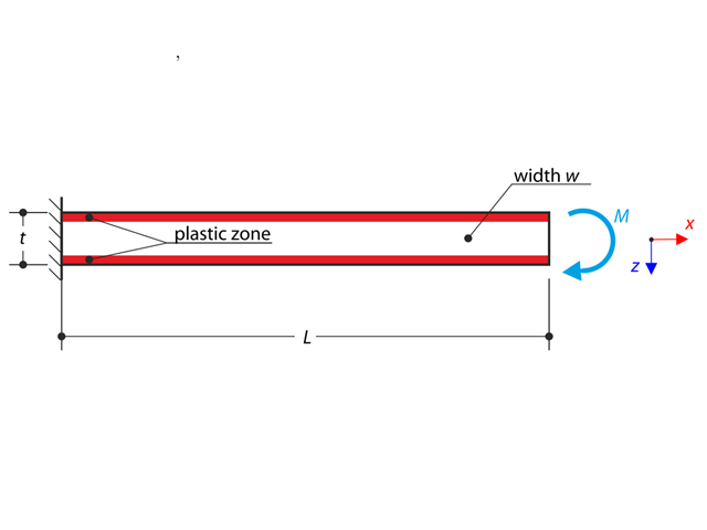
A cantilever is fully fixed on the left end and loaded by a bending moment. Plastic material is considered for the calculation.
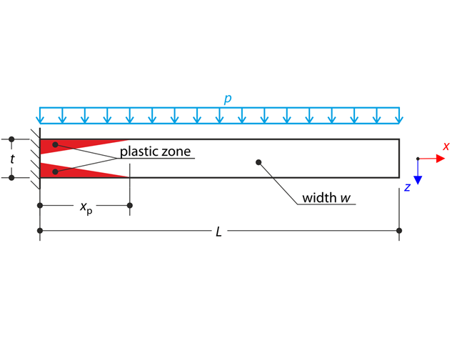
A thin plate is fully fixed on the left end and loaded by uniform pressure. Plastic material is considered for the calculation.
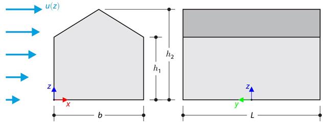
This verification example compares wind load calculations on a duopitch roof building using the ASCE 7-16 standard and using CFD simulation in RWIND Simulation. The building is defined according to the sketch and the inflow velocity profile taken from the ASCE 7-16 standard.

This verification example compares wind load calculations on a flat roof building using the ASCE 7-16 standard and using CFD simulation in RWIND Simulation. The building is defined according to the sketch and the inflow velocity profile taken from the ASCE 7-16 standard.
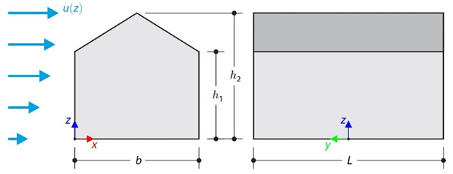
The verification example compares wind load calculation on a building with a duopitch roof using the standard EN 1991-1-4 and using CFD simulation in RWIND Simulation. The building is defined according to the sketch, and the inflow velocity profile is taken according to the standard EN 1991-1-4.
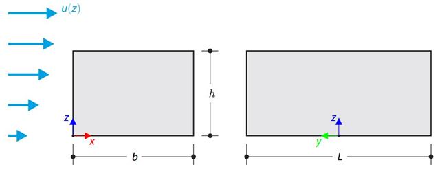
The verification example compares wind load calculation on a building with a flat roof using the standard EN 1991-1-4 and using CFD simulation in RWIND Simulation. The building is defined according to the sketch, and the inflow velocity profile is taken according to the standard EN 1991-1-4.
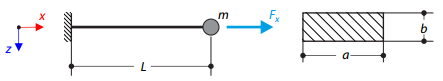
A cantilever of rectangular cross‑section has a mass at the end. Furthermore, it is loaded by an axial force. Calculate the natural frequency of the structure. Neglect the self‑weight of the cantilever and consider the influence of the axial force for the stiffness modification.
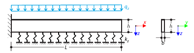
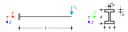
A cantilever from a rectangular cross-section is lying on an elastic Pasternak foundation and loaded by distributed loading. The image shows the calculation of the maximum deflection and maximum bending moment.
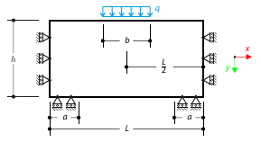
A masonry wall is exposed to a distributed load in the middle of its upper section. The Isotropic Masonry 2D material model is compared with the Isotropic Linear Elastic model, with surface stiffness property Without Tension in the nonlinear calculation.
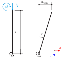
Consider a rigid scaffolding tube, fixed at the bottom using the Scaffolding Nodal Support and loaded by both a moment and a force. Calculate the maximum deflection with consideration of initial slippage.
Consider a rigid scaffolding tube, fixed at the bottom using the Scaffolding Nodal Support and loaded by both a moment and a force. Calculate the maximum radial deflection by exceeding the capacity of the scaffolding support.
Time history analysis of a cantilever beam (SDOF system) excited by a periodic function. Vertical deformations and accelerations calculated with direct integration and modal analysis in RF‑/DYNAM Pro - Forced Vibrations are compared with the analytical solution.
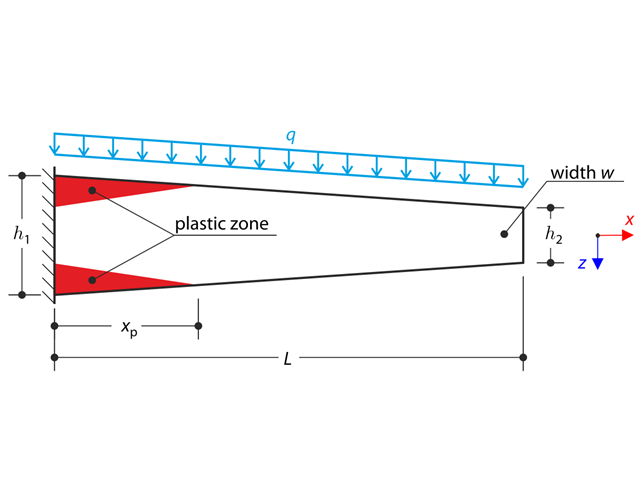
A tapered cantilever is fully fixed on the left end and loaded by a continuous load. Plastic material is considered for the calculation.
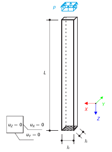
A vertical cantilever with a square cross-section is loaded at the top by tensile pressure. The cantilever consists of an isotropic material. Calculate the deflection.
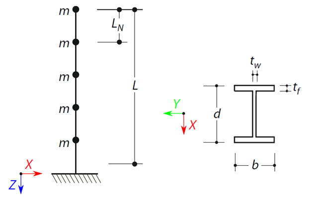
A cantilever beam with an I-beam cross-section of length L is defined. The beam has five mass points with masses m acting in the X-direction. The self-weight is neglected. The frequencies, mode shapes, and equivalent loads of this 5-DOF system are analytically calculated and compared with the results from RSTAB and RFEM.

A cantilever from a rectangular cross-section is lying on an elastic Winkler foundation and loaded by distributed loading. The image shows the calculation of the maximum deflection and maximum bending moment.
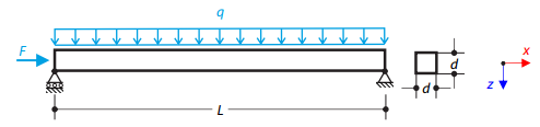
A steel beam with a square cross-section is loaded with an axial force and distributed loading. The image shows the calculation of the maximum bending deflection and critical load factor according to the second-order analysis.
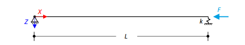
An axially loaded steel beam with a square cross-section is pinned at one end and spring-supported at the other. Two cases with different spring stiffnesses are considered. The verification example solves the calculation of the load factors of the beam in the image using the linear stability analysis.
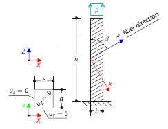
A cantilever with fibers that do not run in direction of the beam axis from a square cross‑section with tensile pressure. Calculate the maximum deflection.