We provide hints and tips to help you get started with the RFEM program.
FAQ 003612 | For cross-section design of a flat steel, I obtain abnormally high shear stresses due to the torsion in the STEEL EC3 add-on module, which can be disproved by a simple manual calculation. What is the error?
Video
First Steps with RFEM
Question
For cross-section design of a flat steel, I obtain abnormally high shear stresses due to the torsion in the STEEL EC3 add-on module, which can be disproved by a simple manual calculation. What is the error?Answer
Most likely, the error is in the selection of the cross-section:
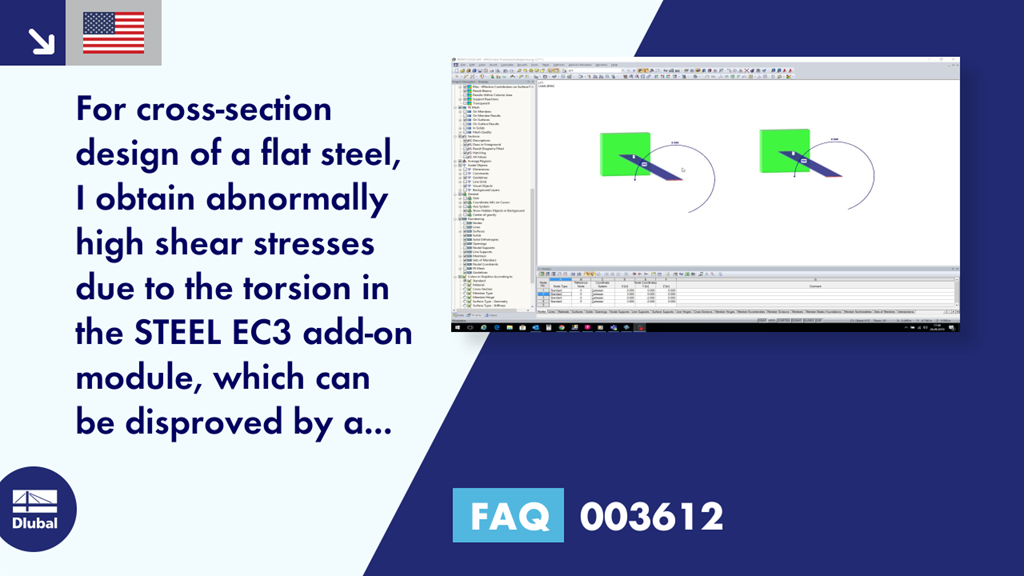
For steel design, a thin-walled flat bar cross-section should be selected instead of a rectangular solid cross-section, see Figure 01.
The reason for the high shear stress of a solid cross-section is caused by the existing stress points of the cross-section or by the corresponding thickness of this stress point.
In the case of a thin-walled flat bar cross-section, there are four stress points at the corner points of the cross-section with the corresponding thickness t = 10 mm, see Figure 02.
Figure 02 - Stress Points of Flat Bar
For a solid cross-section, however, there is another stress point in the center, where the maximum of height h or width b is assumed as the thickness t for this cross-section type. In this case, the width b is 200 mm, see Figure 03.
Figure 03 - Stress Points of Solid Cross-Section
This results in a small torsional section modulus Wt and the correspondingly high shear stress.
The solution is, as described above, to select a flat bar in the main program.
Keywords
Dlubal FAQ Implausible Result Shear stress Torsion Frequently Asked Question FAQ about Dlubal Question and Answer about Dlubal
Links
Write Comment...
Write Comment...
Contact us
Do you have any questions about our products or need advice on selecting the products needed for your projects?
Contact us via our free e-mail, chat, or forum support or find various suggested solutions and useful tips on our FAQ page.
Recommended Events
Videos
Models to Download
Knowledge Base Articles

New
Consideration of the net cross-section for tensile stress according to EN 1993-1-1
When connecting tension -loaded components with bolted connections, the cross -section weakening due to the bolt holes must be considered in the ultimate limit state design. The following article describes how the design of the tension resistance according to DIN EN 1993-1-1 can be performed with the net cross-section area of the tension member in the RF-/STEEL EC3 add-on module.
Screenshots
Product Features Articles

SHAPE-THIN | Cold-Formed Sections
SHAPE-THIN determines the effective cross-sections according to EN 1993-1-3 and EN 1993-1-5 for cold-formed sections. You can optionally check the geometric conditions for the applicability of the standard specified in EN 1993‑1‑3, Section 5.2.
The effects of local plate buckling are considered according to the method of reduced widths and the possible buckling of stiffeners (instability) is considered for stiffened sections according to EN 1993-1-3, Section 5.5.
As an option, you can perform an iterative calculation to optimize the effective cross-section.
You can display the effective cross-sections graphically.
Read more about designing cold-formed sections with SHAPE-THIN and RF-/STEEL Cold-Formed Sections in this technical article: Design of a Thin-Walled, Cold-Formed C-Section According to EN 1993-1-3.
Frequently Asked Questions (FAQ)
- How can I design any SHAPE‑THIN cross-section in detail in RFEM or RSTAB?
- I compare the flexural buckling design according to the equivalent member method and the internal forces according to the linear static analysis with the stress calculation according to the second-order analysis including imperfections. The differences are very large. What is the reason?
- For cross-section design of a flat steel, I obtain abnormally high shear stresses due to the torsion in the STEEL EC3 add-on module, which can be disproved by a simple manual calculation. What is the error?
- I cannot see any members if the RF-/STEEL EC3 add-on module is selected as a "load case," why?
- To which axes refer the support rotations and support eccentricities in RF‑/STEEL EC3 Warping Torsion?
- What does the load application point in RF-/STEEL EC3 Warping Torsion refer to?
-
When designing a beam, I would like to neglect the torsion included in the stability analyses using the filters described in Knowledge Base Article #001498.
I define the filter, but the torsion warning appears at the same x‑location again. Do the design internal forces change, or why is that? -
What are the options in RFEM or RSTAB for determining the ideal elastic critical moment for any cross-sections and systems/loads?
Is it also possible to design flat steel (brackets, flat steel stringers of staircases)? - I perform a stability analysis according to the second-order analysis. Why is the partial safety factor γM1 used for the stress analysis here?
- I would like to design banisters so I have created a set of members for this. The cross-section is a hollow section. Is it possible to carry out the stability analysis on the entire structure or do I have to convert it with the data of all supports to the equivalent member design in STAHL EC3?