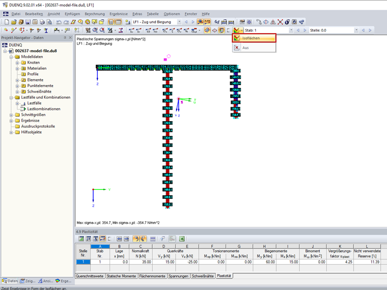
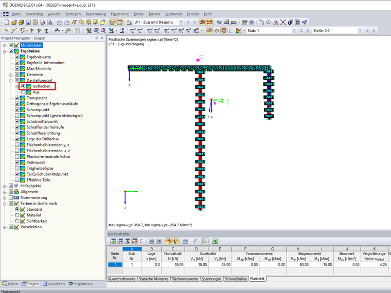
Contact us
Did you find your question?
If not, contact us via our free e-mail, chat, or forum support, or send us your question via the online form.
Recommended Events
Videos
Models to Download
Knowledge Base Articles

New
Creating Member with Variable SHAPE-THIN Cross-Section
In RFEM and RSTAB, it is possible to analyze members with a variable cross-section, which can also consist of freely defined SHAPE‑THIN cross-sections. For the determination of internal forces and deformations, the cross-section properties are interpolated.
Screenshots
Product Features Articles

SHAPE-THIN | Cold-Formed Sections
SHAPE-THIN determines the effective cross-sections according to EN 1993-1-3 and EN 1993-1-5 for cold-formed sections. You can optionally check the geometric conditions for the applicability of the standard specified in EN 1993‑1‑3, Section 5.2.
The effects of local plate buckling are considered according to the method of reduced widths and the possible buckling of stiffeners (instability) is considered for stiffened sections according to EN 1993-1-3, Section 5.5.
As an option, you can perform an iterative calculation to optimize the effective cross-section.
You can display the effective cross-sections graphically.
Read more about designing cold-formed sections with SHAPE-THIN and RF-/STEEL Cold-Formed Sections in this technical article: Design of a Thin-Walled, Cold-Formed C-Section According to EN 1993-1-3.
Frequently Asked Questions (FAQ)
- What is the purpose of a fillet weld in SHAPE‑THIN?
- How can I display shear stresses on null elements in SHAPE‑THIN?
- When calculating a cross-section, I get a message saying that the weld is not connected to two elements. What should I do?
- I would like to calculate the results, such as ordinates, static moments, stresses, at a specific location of a cross-section. What should I do?
- How can I calculate stresses in SHAPE‑THIN?
- During the calculation, I get a warning that some elements are connected to the buckling panel, but are not defined as stiffeners (Figure 1). What should I do?
- In the RF‑/STEEL EC3 add-on module, I obtain an extremely high design ratio for a member in the case of "Biaxial bending, shear and axial force." Although the axial force is relatively high, the design ratio seems to be unrealistic. What is the reason?
- Why do I get such a small amount of reinforcement for the upstand beam? The amount of reinforcement for the downstand beams is significantly larger.
- How are the creep and shrinkage for columns considered in RF‑CONCRETE Members?
- For a buckling analysis, FE‑BUCKLING determines the governing shear stress of τ = 7.45 kN/cm², while RF‑/STEEL gives the result of the maximum shear stress of τ = 8.20 kN/cm². Where does this difference come from?