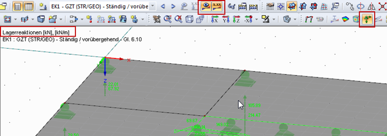
- Check to see if the results of the selected load case have been calculated and the support reactions have been activated (see Image 01).
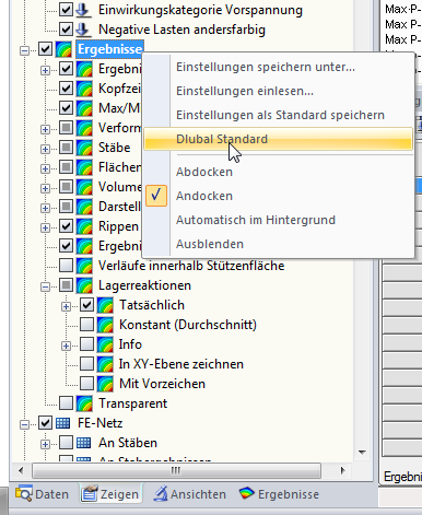
- If this did not work, the settings in the Display navigator probably caused the problem. In this case, we recommend resetting the settings in the Display navigator to the default settings; to do this, first open the Display navigator. Then, right-click the entry in the navigator and open the shortcut menu shown in the graphic below. In the shortcut menu, you can select the "Dlubal Default" entry. Thus, the settings are reset to the default value and the display of support forces should work again.
Question
I would like to graphically display support loads on my screen. Unfortunately, it no longer works, for some reason.
Use the "Independent mesh preferred" option in the FE mesh settings to create an independent FE mesh for the integrated objects. This allows you to generate a significantly more detailed and precise FE mesh for individual objects that are integrated into one another.
In the "Edit Section" dialog box, you can display the buckling shapes of the Finite Strip Method (FSM) as a 3D graphic.
In RFEM 6 and RSTAB 9, you have the option to enter "Visual Objects" as guide objects. You can import the file formats 3ds, stl, and obj.
These objects allow you to create a better reference to the dimensions.
Do you have individual column sections and angled wall geometries, and need punching shear design for them?
No problem. In RFEM 6, you can perform punching shear design not only for rectangular and circular sections, but for any cross-section shape.