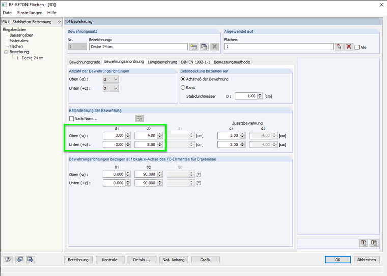
If only the ultimate limit state is considered, a different concrete cover per reinforcement direction can be defined in RF‑CONCRETE Surfaces (see Image 01). Once the serviceability limit state is also designed, both reinforcement directions must be adjacent to each other. The different concrete cover by reinforcement direction can no longer be taken into account.
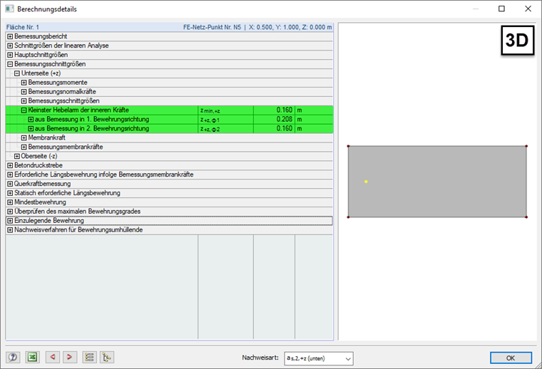
Consideration of 3D Design – Shell
In the case of the design in a 3D structure, the element is considered as a shell. Both the moments and axial forces can act here, which are transformed into the design membrane forces. These design membrane forces are then used to determine the required reinforcement. In connection with the transformation from moments and axial forces, the smaller lever arm from both reinforcement directions is applied. Thus, only one governing lever arm is assumed for both directions.
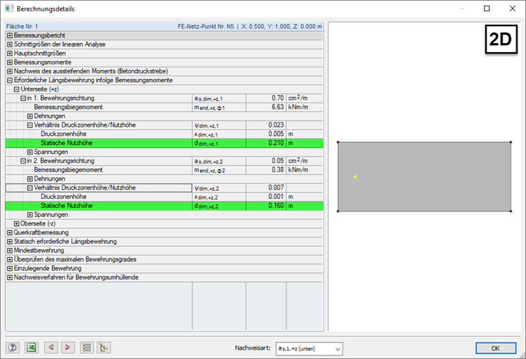
Consideration 2D Design – Slab
In the case of the design in a 2D structure, the surface element is considered as a slab. The only moments that act are those that are designed with the corresponding lever arm of the direction. Thus, each direction is supposed to have its respective lever arm.