The default definition of surface elements assumes isotropic material behavior. The load attempts to get to the supports as quickly as possible. The stiffness of the elements also plays a role here.
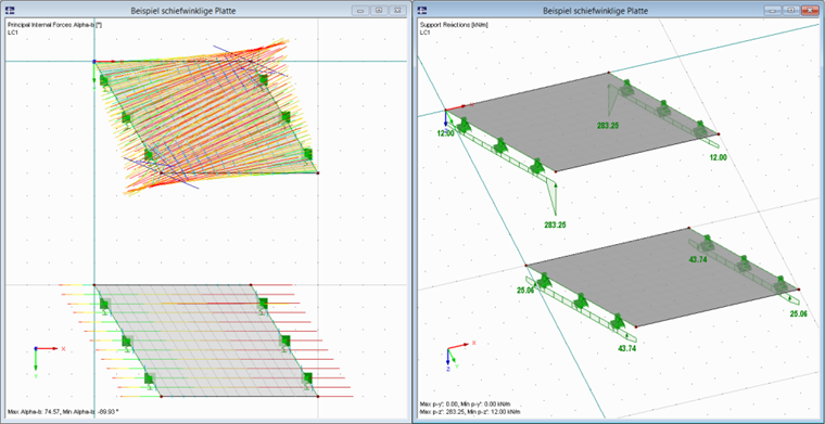
In the case of plates, the best way to display and represent the structural behavior or the load transfer is to use the trajectories of the principal moments αb. For wall elements, it is necessary to consider the trajectories of the principal axial forces αm.
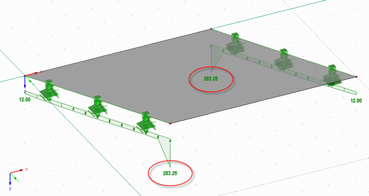
In this example, the load is not transferred parallel to the free edges of the plate, but almost perpendicularly to the supports, as this is the shortest path of load transfer.
At the dulled corners of the structure, the load application area is larger than in the support centers, corresponds to a singularity point, and as a result, it has great peak values.
In order to force the system to remove the load parallel to the free plate edges, the following procedure is the fastest:
Definition of an orthotropic plate. We recommend using the "Effective Thicknesses" orthotropy type. The effective plate thickness has to be specified in the support direction and a very small thickness in the secondary support direction (for example, 1 mm).
The second image shows the difference between both models.