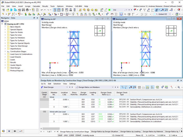
16 Results
View Results:
Sort by:

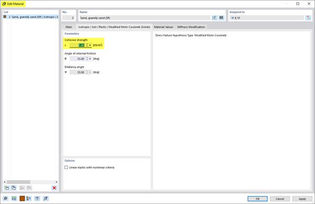
Structure Below Ground Level
Why does the integration/support of my building in the ground below the ground level not work?

Adjusting NDS and CSA O86 Factors for Consideration in the Timber Design Add-on
How can the NDS and CSA O86 factors be manually adjusted for consideration in the Timber Design add-on?
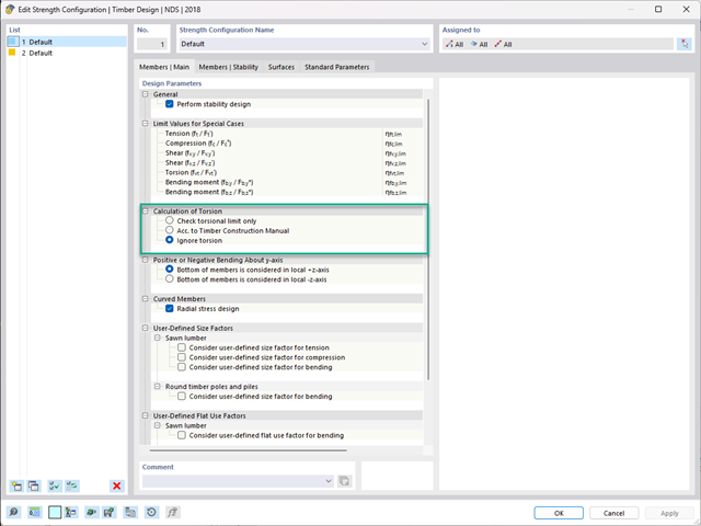
NDS Strength Configuration - Calculation of Torsion Settings
What calculation is carried out for the NDS Strength Configuration "Calculation of Torsion" options?
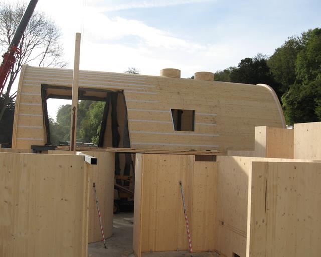
Programs for Laminate and CLT Structures
Which programs do I need for laminate and sandwich structures, or cross-laminated timber (CLT)?
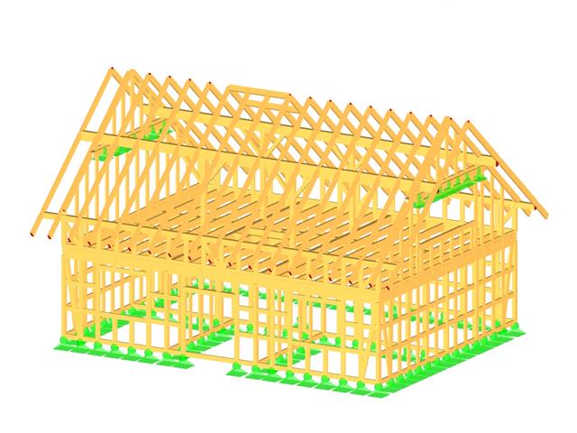
Programs for Timber Structures
Which Dlubal Software programs can I use to calculate and design timber structures?
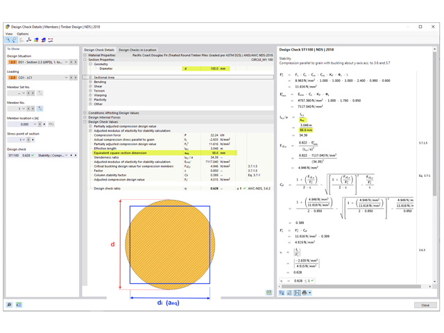
Equivalent Round Section Dimension
How is the dimension for an equivalent round section calculated in the Timber Design add-on?
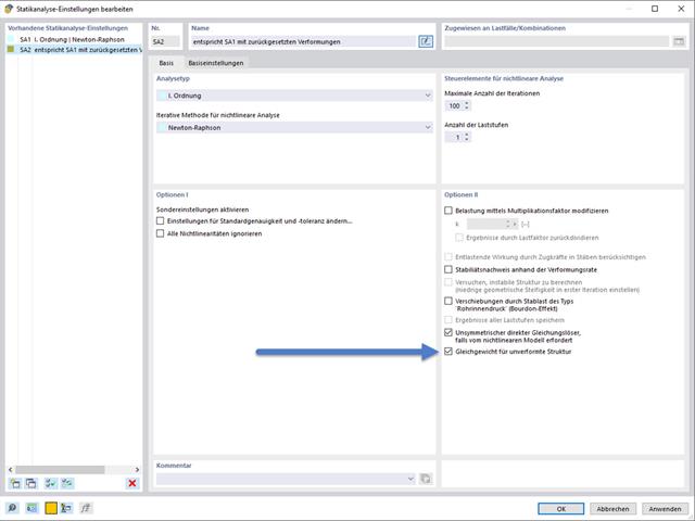
Setting Deformations to 0
How can I set the deformations from an LC/CO or a construction stage to 0?