The structural analysis software RFEM 6 is the basis of a modular software system. The main program RFEM 6 is used to define structures, materials, and loads of planar and spatial structural systems consisting of plates, walls, shells, and members. The program also allows you to create combined structures as well as to model solid and contact elements.
RSTAB 9 is a powerful analysis and design software for 3D beam, frame, or truss structure calculations, reflecting the current state of the art and helping structural engineers meet requirements in modern civil engineering.
Do you often spend too long calculating cross-sections? Dlubal Software and the RSECTION stand-alone program facilitate your work by determining section properties of various cross-sections and performing a subsequent stress analysis.
Do you always know where the wind is blowing from? From the direction of innovation, of course! With RWIND 2, you have a program at your side that uses a digital wind tunnel for the numerical simulation of wind flows. The program simulates these flows around any building geometry and determines the wind loads on the surfaces.
Are you looking for an overview of snow load zones, wind zones, and seismic zones? Then you are in the right place. Use the Geo-Zone Tool to determine quickly and efficiently snow loads, wind speeds, and seismic data according to ASCE 7‑16 and other international standards.
Would you like to try out the capabilities of the Dlubal Software programs? You have the opportunity to do so! The free 90-day full version allows you to thoroughly test all our programs.
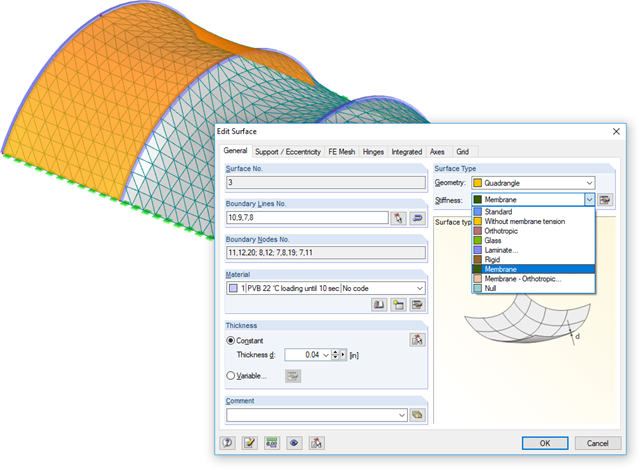
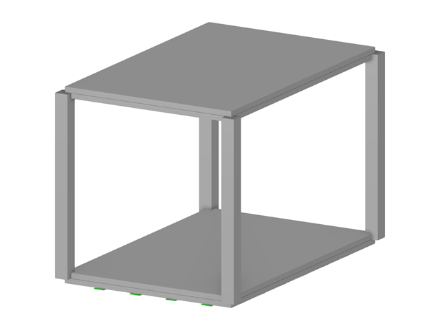
In RFEM, it is possible to define a surface of the Membrane type (see the image). The calculation is then done automatically according to the large deformation analysis.
For the modeling of membrane structures, we recommend the Form-Finding add-on (for RFEM 6) or the RF-FORM-FINDING add-on module (for RFEM 5).
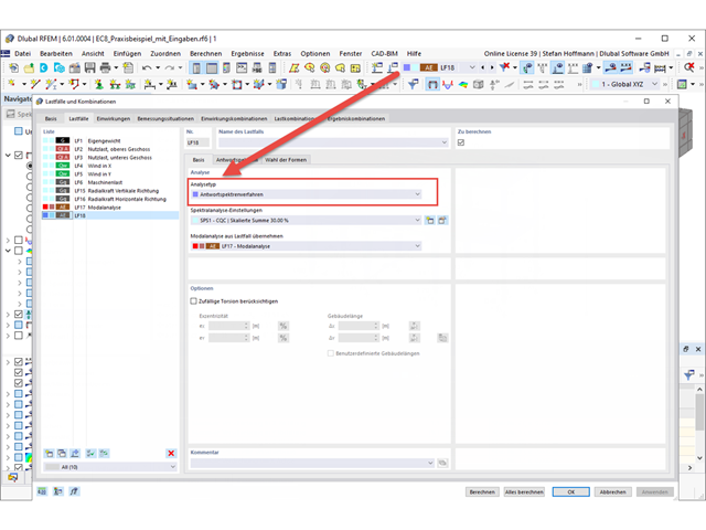
To perform an earthquake analysis, you need a modal analysis and then a load case of the Response Spectrum Analysis type.
After you have performed your modal analysis, create a new load case. Here you will find the usual settings from the previous program generation.
In the Response Spectrum tab, you can define your response spectrum as usual. If you want to use a response spectrum according to the standard, make sure that the desired standard is selected in the general data of Standards II.
In the Selection of Modes tab, you can select the mode shapes and filter them, if necessary.
After the load case has been calculated, you obtain the results.
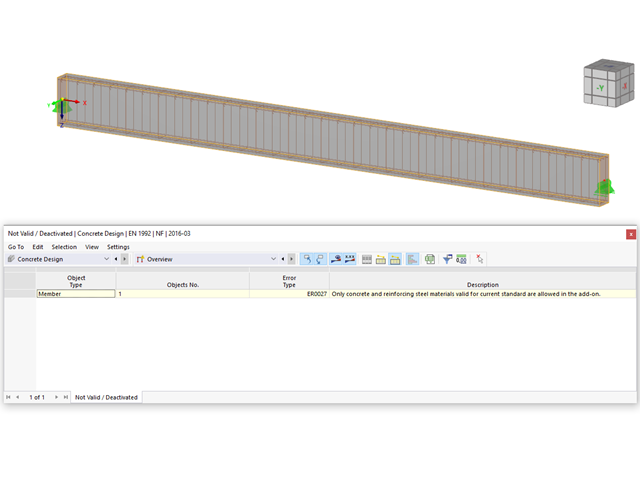
Check to see if the material assigned to the members is compatible with the standard selected for the design in the "Concrete Design" add-on.
Furthermore, please check to see if all design properties (durability class, concrete cover, shear and longitudinal reinforcement, and so on) have been specified correctly in the "Edit Member" dialog box.
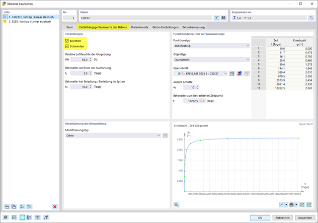
You can activate the creep and shrinkage to be considered for the concrete design in the Edit Material dialog box (see Image 01).
Once you activate the creep and/or shrinkage for the material, there is the option to define "Advanced Time-Dependent Properties of Concrete" in the dialog boxes for the cross-sections and thicknesses using this material. Select this check box and then define the parameters for the creep or shrinkage in the corresponding tab (see Image 02).
Further information can be found in the chapter of the Concrete Design online manual at the link below.
No, this is not possible in the current state of development of RFEM 6.
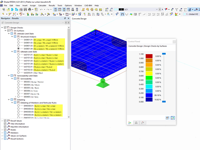
See also the FAQ for RFEM 5 and RF‑CONCRETE Surfaces by clicking the link below.The design concept is currently structured similarly and is based on the reinforcement on the top and bottom sides.
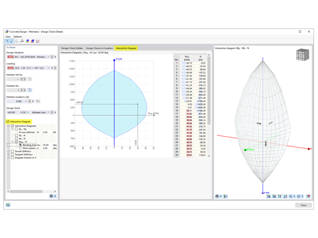
To display the interaction diagram, open the "Design Details" dialog box of Concrete Design.
On the left side of the dialog box, you can then select the "Interaction Diagram". Thus, an additional tab called "Interaction Diagram" appears. You can control the settings for the result display here.
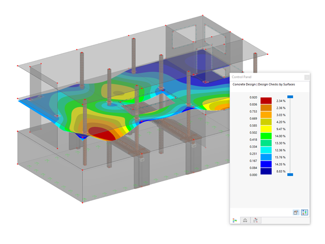
Yes, the deformation analysis taking into account the cracked state in the cross-section is included in the concrete design in RFEM 6.
For this, the effective stiffness is calculated for each element in the concrete design according to the existing cross-section state of cracked (state II) or uncracked (state I), and then used in a second FEM calculation for the deformation.
In RFEM 5, this corresponds to the solution in the "RF‑CONCRETE Deflect" add-on module. In RFEM 6, this method is included in the concrete design.
Further information about determining the crack state as part of the deformation analysis can be found in the technical article at the following link.
Masses can be neglected in the modal analysis settings.
It is possible to neglect masses in all fixed nodal supports and line supports, or to create a selection of the individual objects.
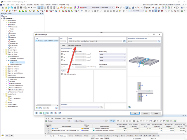
The Masonry Design add-on allows you to automatically determine the stiffness of your wall-slab hinge. The diagrams were determined as part of the research project DDmaS - "Digitizing the design of masonry structures" and are derived from the standard.
Define a line hinge on the connection line of both surfaces and activate the slab-wall connection.
You can now enter your parameters in the Slab-Wall Connection tab. Then, click the Regenerate [...] button.
The determined diagrams are displayed subsequently.