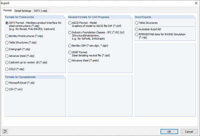
The structural analysis software RFEM 6 is the basis of a modular software system. The main program RFEM 6 is used to define structures, materials, and loads of planar and spatial structural systems consisting of plates, walls, shells, and members. The program also allows you to create combined structures as well as to model solid and contact elements.
RSTAB 9 is a powerful analysis and design software for 3D beam, frame, or truss structure calculations, reflecting the current state of the art and helping structural engineers meet requirements in modern civil engineering.
Do you often spend too long calculating cross-sections? Dlubal Software and the RSECTION stand-alone program facilitate your work by determining section properties of various cross-sections and performing a subsequent stress analysis.
Do you always know where the wind is blowing from? From the direction of innovation, of course! With RWIND 2, you have a program at your side that uses a digital wind tunnel for the numerical simulation of wind flows. The program simulates these flows around any building geometry and determines the wind loads on the surfaces.
Are you looking for an overview of snow load zones, wind zones, and seismic zones? Then you are in the right place. Use the Geo-Zone Tool to determine quickly and efficiently snow loads, wind speeds, and seismic data according to ASCE 7‑16 and other international standards.
Would you like to try out the capabilities of the Dlubal Software programs? You have the opportunity to do so! The free 90-day full version allows you to thoroughly test all our programs.
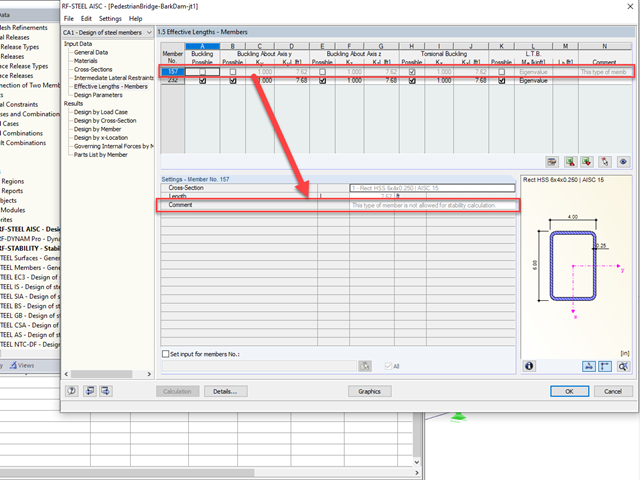
Curved members cannot be designed for stability within the RF-STEEL AISC module. These stability checks include flexural buckling (strong axis and weak axis) and flexural torsional buckling according to Chapter E. Lateral torsional buckling is also not checked according to Chapter F for these types of members.
A possible workaround to carry out stability design for a curved member is to convert the line element to a polyline and design as a straight member instead. Alternatively, a series of straight line segments can be modeled and convert to a set-of-members which can also be designed in the RF-STEEL AISC module including stability checks.
No, load generation, such as "Surface Load on Members via Plane", only works for straight or articulated straight members.
If necessary, curved members can be converted into polygonal members as follows:
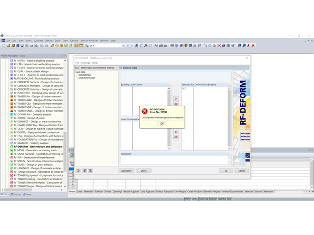
In RF‑DEFORM, you can only design members that are defined on a single line. Otherwise, the error message shown in Image 01 appears.
You can use the "Explode Polyline" function to decompose the polyline (Image 02). For straight lines, we recommend deleting the redundant intermediate nodes (Image 03). Then, deformation analysis in RF‑DEFORM is possible.
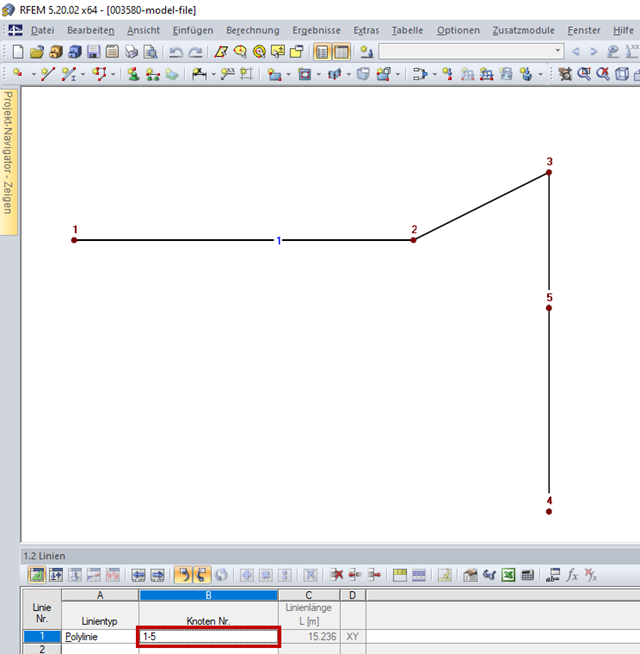
The polyline displayed in Figure 01 has been created in the order of Nodes 1 → 2 → 3 → 4 → 5. This is also visible in Column B "Node No." of Table "1.2 Lines". Thus, the line segments between Nodes 3, 4 and Nodes 4, 5 are overlapping, so that the error message shown in Image 02 appears.
The order of the nodes must be changed in a way so that no line segments overlap each other. In this example, it would be the order of Nodes 1 → 2 → 3 → 5 → 4, as shown in Image 03.
You can also use the "Explode Polyline" function to decompose the polyline (Image 04). Thus, two lines are created between Node 5 and Node 4. Then, you can delete the line. For this, it is also possible to use the "Regenerate Model" function in the "Tools" menu.
Both procedures are shown in the video.
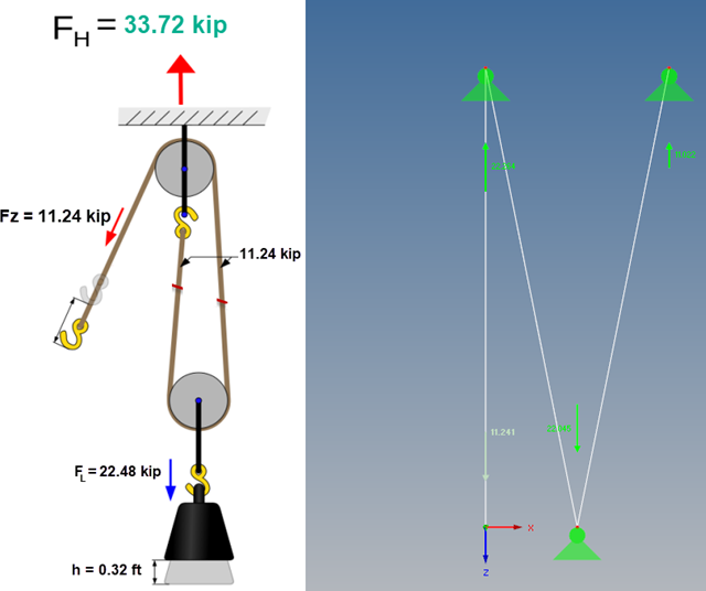
In RFEM, you can simulate a pulley using the "Cable on Pulleys" member type. In this way, it is possible to calculate pulley systems, for example.
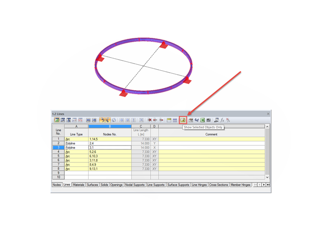
It is necessary to ensure that the member, including all buckling points, only consists of one polyline (see the image). Otherwise, the model would be suspended on nodal supports and no force deflection would occur at these points.