The structural analysis software RFEM 6 is the basis of a modular software system. The main program RFEM 6 is used to define structures, materials, and loads of planar and spatial structural systems consisting of plates, walls, shells, and members. The program also allows you to create combined structures as well as to model solid and contact elements.
RSTAB 9 is a powerful analysis and design software for 3D beam, frame, or truss structure calculations, reflecting the current state of the art and helping structural engineers meet requirements in modern civil engineering.
Do you often spend too long calculating cross-sections? Dlubal Software and the RSECTION stand-alone program facilitate your work by determining section properties of various cross-sections and performing a subsequent stress analysis.
Do you always know where the wind is blowing from? From the direction of innovation, of course! With RWIND 2, you have a program at your side that uses a digital wind tunnel for the numerical simulation of wind flows. The program simulates these flows around any building geometry and determines the wind loads on the surfaces.
Are you looking for an overview of snow load zones, wind zones, and seismic zones? Then you are in the right place. Use the Geo-Zone Tool to determine quickly and efficiently snow loads, wind speeds, and seismic data according to ASCE 7‑16 and other international standards.
Would you like to try out the capabilities of the Dlubal Software programs? You have the opportunity to do so! The free 90-day full version allows you to thoroughly test all our programs.
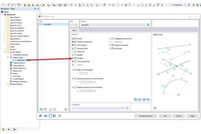
Under the Guide Objects category, you can edit the object snap. The "Tangent" option can be activated in the settings of the object snap. If you want to design a straight line on a circle, the snap point on the circle for a tangent is also displayed now.
There are two different options for doing this.
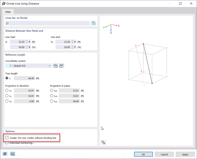
Option #1:Right-click the line and use the "Divide Line" tool. In the following dialog box, select the "Create 'On Line' nodes without dividing line" option.
Option #2: Manually draw a node and snap to the intersection point.
Double-click this node to edit it and change it to an "On Line" node type.
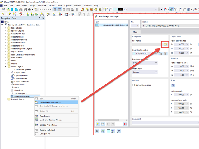
RFEM and RSTAB provide the option to import DXF files as background layers. You can then use them as guide objects and thus achieve fast and efficient modeling.
The easiest way to import a DXF file as a background layer is to use the Data navigator. You can insert a new background layer via "Auxiliary Objects" → right-click on "Background Layers" → "New Background Layer...", see Image 01. A dialog box appears, where you select the DXF file from your own files.
Furthermore, it is possible to move the background layer in the model area, rotate it, and scale it in all three spatial axes. Moreover, the background layers can be set to active or inactive, as required. Image 02 shows the dialog box for inserting/editing a background layer.
Select the insertion point manually in the preview.
As of the version X.02.0069, it is also possible to select the insertion point of the DXF layer directly in the preview window.
To do this, activate the "Select in Preview" option and select the "Pick" button on the right in the "Origin Point" area. All object snaps are then available in the preview window to select the desired insertion point, see Image 03.
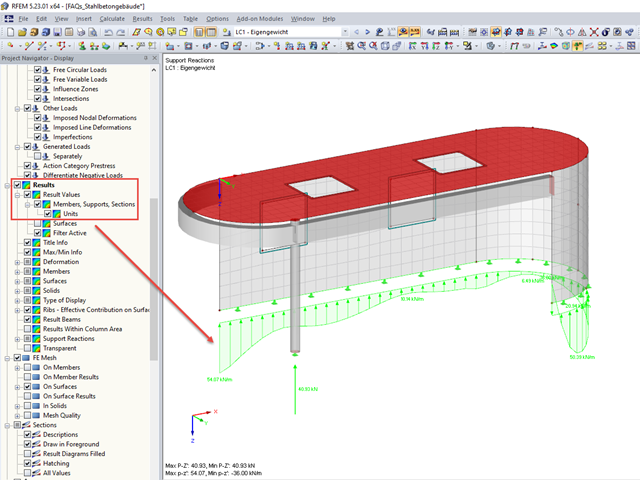
The units of the node and line supports can be seen in the max/min info. For the support forces, for example, the unit kN/m is used, and for the support moments, kNm/m.
The note about this is not preset in the graphic because the results of internal forces can also be displayed in the graphic at the same time. To activate the output of units, select "Result Values" under "Results" in "Project Navigator - Display".
The value refers to a distance of 1 m.
A partial value is specified in each FE Mesh Node. A snapshot (so to speak) of the line support is displayed.
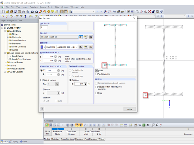
The offset point of the section is used as a reference point to place the section in the cross-section. This point is highlighted in red in the section graphic of the "Set Section" dialog box (Image 01). Coordinates y and z refer to the centroid of the section.
Another reference point can be selected by clicking one of the red nodes, or turquoise snap points can be defined. At this point, the section is "glued" to the pointer before it is finally set with a mouse click.
A clever choice of section offset point makes it easier to set the section on elements. This is also shown in the video. Please note that the sections shown in the video are not yet connected to each other. The way these can be connected is shown in FAQ 002389.
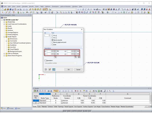
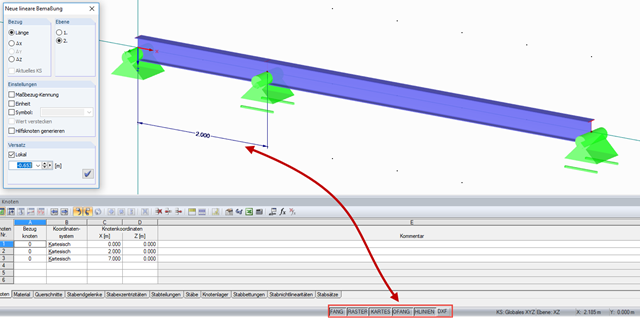
The coordinates of guidelines (Image 01) to be specified in the "New Guideline" dialog box under "Parameters" refer to the zero point of the work plane.
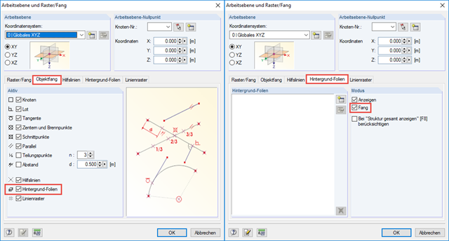
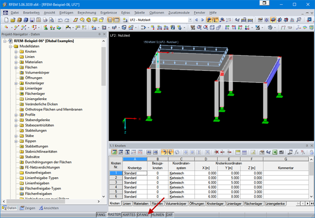
You can set the zero point of the work plane in the "Work Plane and Grid/Snap" dialog box (Image 02) using the menu Tools→ Select Work Plane → Set Origin or the corresponding button in the toolbar.
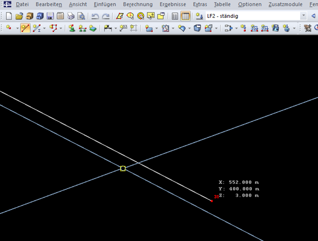
In the video, the zero point of the work plane is set to the coordinates X = 3 m, Y = 5 m, and Z = 0 m. Then, a guideline is created parallel to X (|| to X) with the coordinate y1 = 0 m. Thus, the guideline is in the global coordinate system at Y = 5 m.