Stress Point Parameters
The following characteristic values of a stress point are used to determine the stresses:
- Coordinates related to the centroid of the cross-section (for normal stresses from axial force and bending moments)
- Static moments (for shear stresses from shear forces)
- Thickness (for shear stresses from shear forces and torsional moment)
- Core area for closed cross-sections (for shear stresses from torsional moment)
Shear Stresses
For thin-walled cross-sections, we can assume as a simplification that the shear stress runs parallel to the wall of the cross-section. Therefore, the parts of the shear stresses resulting from both components of the shear forces are added. The sign of the statical moments defines here which parts are applied positively and which negatively.
The shear stress due to the torsional moment is to be considered differently for the total shear stress, depending on whether it is an open or closed cross-section. In the case of an open section, the torsional shear stress is added with its sign to the sum of the individual shear stresses that results in the greater absolute value of the sum. For a closed section, however, the torsional shear stress is simply added to the sum resulting from the individual shear stresses. Here, the signs for core area and statical moments are set in such a way that they correspond to the program-specific sign conventions of the shear stress that is dependent on the loading.
Double Stress Points
Stress points located within the cross-section do not permit the assumption mentioned above, that the shear stress runs parallel to the wall of the cross-section. Here, a special method with twin stress points is used, creating two stress points with identical coordinates in the cross-section. One stress point considers the statical moment around the y-axis (parameter for shear stress due to vertical shear force); the other considers the statical moment around the z-axis (parameter for shear stress due to horizontal shear force). For these stress points, the complementary statical moment is equal to zero.
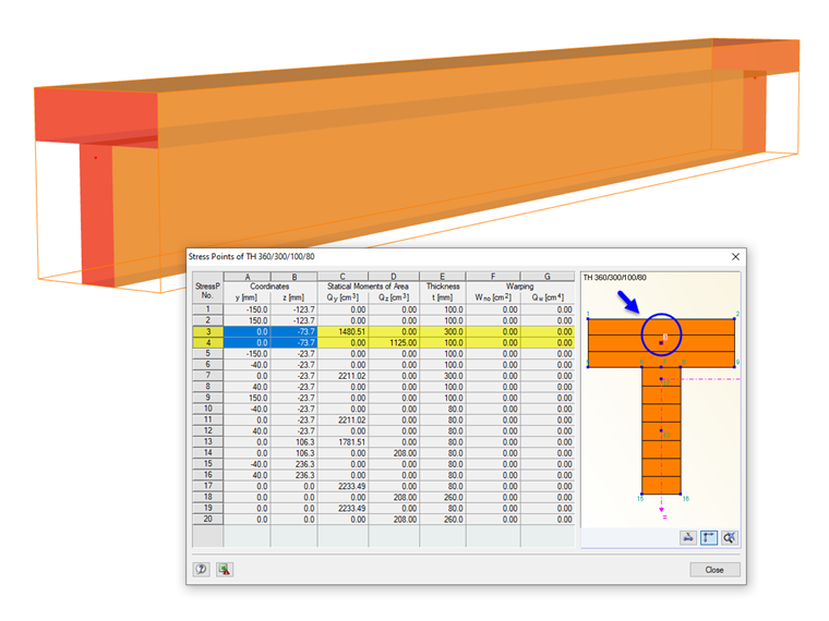
Different thicknesses can be assigned to the twin stress points, which also have an influence on the calculation of the shear stress. The shear stresses are considered as interdependent components acting perpendicular to each other: they are two components of one stress state. For the determination of the total shear stress, both parts are quadratically added. The shear stress due to the torsional moment is not considered in these points.
The shear stresses of result combinations available in the twin stress points may not be combined linearly. Therefore, the extreme values of both components are evaluated with the corresponding complementary shear stresses in order to determine the greatest total shear stress.