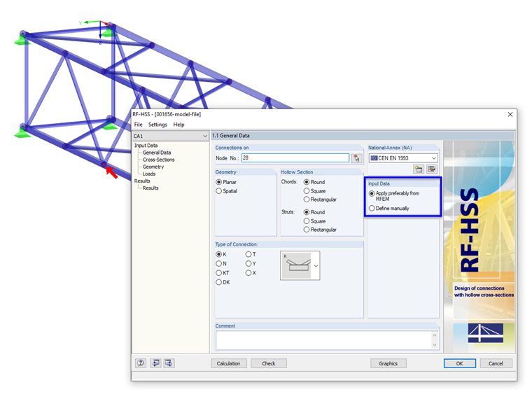
Automatic Data Import or Manual Data Input for Analysis of a Hollow Section Node in RF-/HSS
Tips & Tricks
In the RF‑/HSS add‑on module, you can analyze the connections for nodes at which hollow sections join. In addition to importing the geometry and loads from RFEM or RSTAB, you can also define the nodal parameters manually. Thus, you can also check existing connections without creating the truss model in RFEM or RSTAB.
Keywords
Hollow section Joint Nodal internal forces
Links
Write Comment...
Write Comment...
Contact us
Do you have questions or need advice?
Contact our free e-mail, chat, or forum support or find various suggested solutions and useful tips on our FAQ page.
Recommended Events
Videos
Models to Download
Knowledge Base Articles

New
Design of a welded truss
This technical article deals with the component and cross-section designs of a welded truss in the ultimate limit state. Furthermore, the deformation analysis in the serviceability limit state is described.
Screenshots
Product Features Articles

Material Database with Steels According to the Australian Standard AS/NZS 4600:2005
The material database in RFEM, RSTAB and SHAPE-THIN contains steels according to the Australian standard AS/NZS 4600:2005.Frequently Asked Questions (FAQ)
- Is it also possible to design individual hollow sections using the HSS add‑on module?
- For which programs is the STEEL Warping Torsion add-on module available?
- In the RF‑/STEEL EC3 add-on module, I obtain an extremely high design ratio for a member in the case of "Biaxial bending, shear and axial force." Although the axial force is relatively high, the design ratio seems to be unrealistic. What is the reason?
- I have just noticed that the STEEL EC3 add-on module also calculates with γM0 = 1.0 when designing a tension member, although it should actually be γM2 = 1.25. How can I perform the design correctly?
- I design a cross-section created in the SHAPE‑THIN program by using the RF‑STEEL EC3 add-on module, but the program shows the error message "ER006 Invalid type of c/t-part for cross-section of type General." What can I do?
- Is it possible to design intermittent welds in the CRANEWAY add-on module?
- For a buckling analysis, FE‑BUCKLING determines the governing shear stress of τ = 7.45 kN/cm², while RF‑/STEEL gives the result of the maximum shear stress of τ = 8.20 kN/cm². Where does this difference come from?
- Why do I get a design ratio for the stability analysis according to 6.2.9.1 in the STEEL EC3 add-on module? Why is a * added to Equation (6.36)?
- I design a frame with a taper (docked cross-section). STEEL EC3 classifies the taper in Cross-Section Class 3. Accordingly, the elastic resistances are taken into account, which is very unfavorable. According to the standard, the taper should be categorized in Class 1, and thus the plastic reserve should also be usable.
- When modeling a beam connection to a continuous column, I have the problem that the column flange fails under bending. If I add backing plates in the FRAME‑JOINT Pro add-on module, nothing changes for all design ratios. Why?