


Advantages of Representation Using Rib Member Type in RFEM
Rigidity or flexibility of a downstand beam is considered. Thus its influence on the distribution of internal forces and the deformation can be represented.
Rib Parameters

For the rib in a 3D position, there are two essential parameters. First, there is the integration width that defines the area for the integration of internal forces. For this, the integration area on each side must not exceed several surfaces. Second, the rib alignment has to be defined. The position data refer to the local axis system of the surface, including the rib.
Rib Cross-Section
As a cross-section of the rib, it is necessary to define such a cross-section part, which is additionally available on the surface. For the design of a T-beam, the program generates a gross cross-section of the T-beam.
Determination of Internal Forces for Design
Before the design, the internal forces and the relation to the centroid of the T-beam (usually T-section or L-section) are determined. For this, the internal force component of the plate and the rib component are integrated. The internal forces are integrated as perpendicular to the rib axis.

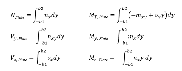
For the plate component, the following internal forces result from the integration of the internal forces in surfaces. It is assumed that the local axis systems of the rib and the surface are the same. If these should not be the same, the internal forces must be previously transformed to the local axis system of the rib.

The internal forces of the rib component correspond to the internal forces of the member including the rib cross-section. In RFEM, it is possible to display the internal forces without the included surface components for the evaluation of internal forces. You can adjust this in Project Navigator - Display under "Results" - "Ribs - Effective Contribution on Surface/Member".

The resulting internal forces of the T-beam are obtained where the internal forces of the plate and rib component refer to the centroid of the T-beam section.

The bending moment of the resulting T-beam can be obtained for a T-section, for example, as follows:
My = My,plate + My,rib - eplate ∙ Nplate + erib ∙ Nrib
The program always determines the resulting internal forces of T-beam sections in accordance with the default setting.
Rib in 2D
Basically, it is not a purely two-dimensional problem in the case of T-beams. Users need to be aware that the consideration of ribs in 2D comes necessarily with a simplification. Since the alignment of eccentric elements is not possible in 2D, the centroidal axis of the T-beam section runs in the surface plane. This approach requires additional steps when considering the stiffness of the structure.

In addition to the parameters of the rib in 3D, further parameters of the rib in 2D have to be applied in order to consider the stiffness of the T-beam section. By internally considering the rib in 2D, the superimposing stiffness results in the integration width area b1 and b2. Therefore, the reduction of the surface stiffness in the integration width area is active due to the default setting of the rib parameters. However, you should note that this application leads to the stiffness concentration along the rib axis, which thus does not occur in reality nor in the display of the rib in 3D.

Since the eccentricity in 2D cannot be displayed, the influence of the eccentricity on the stiffness (that is, the additional Steiner components) is considered. For torsional stiffness, the part of the T-beam section and the surface are superimposed. The torsional stiffness activity of the T-beam section can be reduced manually. Generally, it is not possible to specify a reduction factor or a percentage value for the effective torsional stiffness because this depends on the cross-section geometry.
Therefore, it is better to use the 3D version of RFEM instead of the 2D version to represent the downstand beams.