


Structural System and Loading
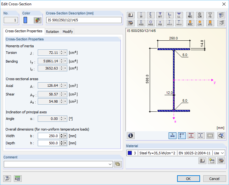
Cross-section: symmetrical welded I-section, structural steel with the yield strength fy = 35.5 kN/cm² (corresponds to S355 or Grade 50)
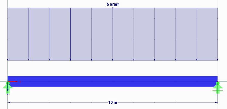
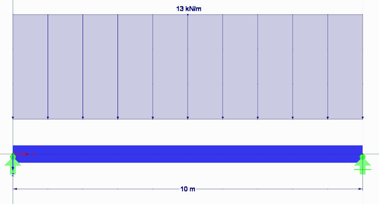
Load combinations:
LC1 = 1.35 LC1 + 1.50 LC2 (Eurocode design)
LC2 = 1.20 LC1 + 1.60 LC2 (AISC design)
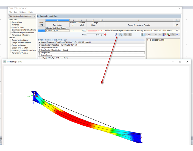
Design According to Eurocode 3
For the design according to Eurocode 3 [1], Load Combination 1 was created and selected for the design in RF‑/STEEL EC3. As the design is to be performed in compliance with the standard regulations, the National Annex (NA) CEN is selected in Window 1.1 General Data.
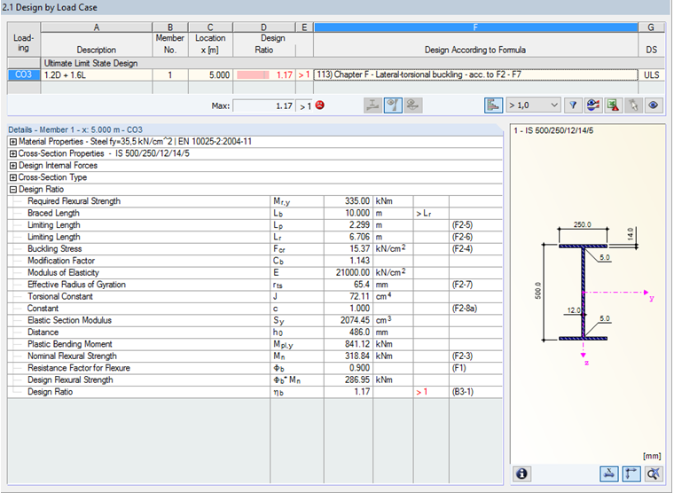
The next windows do not require any changes. The design can be started directly. The design is not fulfilled with the design ratio of 145%. The mode shape shows the lateral-torsional buckling as a critical buckling shape.
Design According to AISC
For the design according to AISC [2], Load Combination 2 was created and selected for the design in General Data of RF‑/STEEL AISC in the same way as for the previous design. The design is performed according to LRFD 2016.
The default settings can be accepted in the next input windows. It is only necessary to select Table F1‑1 for the modification factor Cb in Window 1.7 Design Parameters. The design is also not fulfilled with the ratio of 117% in RF‑/STEEL AISC.
In both add-on modules, the design is not fulfilled. Now, the beam should be provided with a lateral support on the upper chord in the middle.
Stabilization and Design According to Eurocode 3
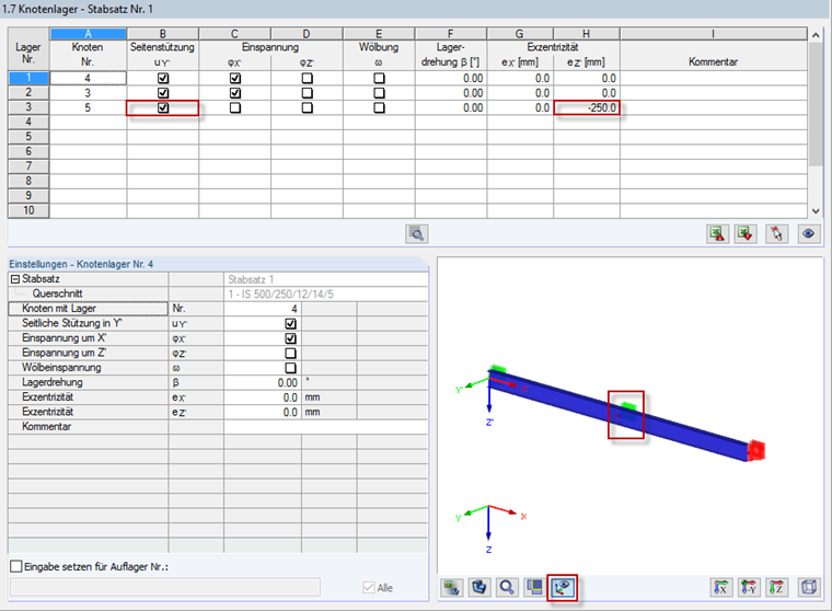
The stabilization in RF‑/STEEL EC3 can be carried out using both the lateral intermediate supports as well as the nodal supports. Since it is only possible in RF‑/STEEL AISC to enter eccentric nodal supports, the same approach is to be used in this example. First, the individual member is divided by an intermediate node and defined as a set of members.
This set of members is to be designed in RF‑/STEEL EC3 according to Eurocode 3 (CEN). By default, the design of sets of members is performed according to Section 6.3.4 General Method in compliance with EN 1993‑1‑1. In order to define the eccentric support of the upper chord, the support uY' with the eccentricity ez' of -250 mm (upper chord) is defined on the intermediate node in Window 1.7.
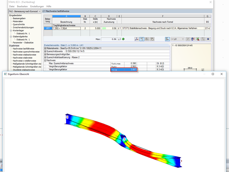
The design is fulfilled with 56% and the resulting critical load factor αcr,op is 3.067. The mode shape of the beam shows a multi-shaft buckling mode due to the stabilization.
Stabilization and Design According to AISC
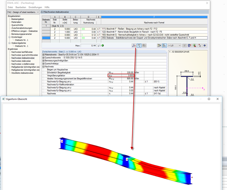
The stabilization in RF‑/STEEL AISC is carried out similarly as in RF‑/STEEL EC3, by entering an eccentric nodal support on the intermediate node. In RF-/STEEL AISC, the design is also fulfilled with the resulting ratio of 44% and the critical load factor of 3.003. The mode shape also shows a multi-shaft buckling mode.
Summary
Due to the consistent entries in the add-on modules, it is possible to perform the design with different design requirements without extensive training. Here, the graphical input options facilitate the verification. In both modules, the structure to be designed can be stabilized, which leads to an efficient result.