


In order to obtain a meaningful assessment of the selected modeling approach, it can be very helpful to first create a model that can be compared to the tried-and-tested methods.
In a previous article, the design resistance of a rigid end plate connection was calculated with the formula according to EN 1993‑1‑8 [1].
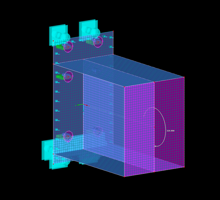
In this example, the design resistance of the end plate should be loaded by means of an FEM modeling approach with the determined design resistance of 324.95 kNm.
Surface Model
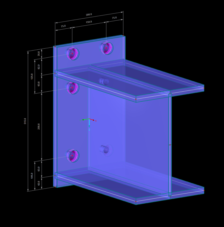
The HEB-400 beam was entered with a length of 500 mm and divided into surfaces. Assuming that the end plate has a rigid behavior under the solid bolt heads, a rigid surface with a washer diameter of 44 mm was generated. To simulate the elasticity of the bolts under tensile stress, they were defined with a diameter of 24 mm and a length of 29 mm (= thickness of end plate + thickness of washer). To ensure that the load is introduced equally into the beam, a rigid end plate was used at the load application location.
Since a rigid support in the z-axis of the end plate can lead to convergence problems, a surface foundation with 2 ∙ 108 kN/m³ was assumed, and an additional line support was provided at the locations where no deformation can occur due to the symmetry conditions of a beam joint or where the greatest support forces are expected. Both supports are intended to fail if the support reaction is positive. Since EN 1993‑1‑8 [1] performs a plastic design, the "Isotropic Plastic 2D/3D" material model with the yielding criterion 23.5 kN/cm² was selected. As soon as the yield criterion is reached in the FE element, it cannot absorb further forces and a stress redistribution takes place.
Results
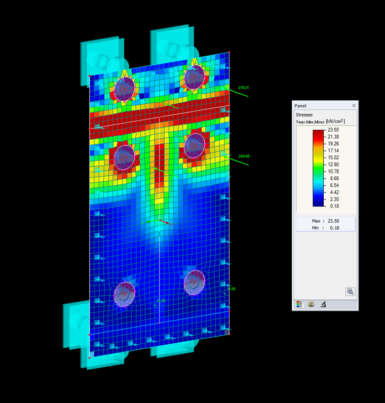
The failure criterion "Bolt failure with yielding of the flange" of the manual calculation can be validated.
When using the nonlinear material model "Isotropic Plastic 2D/3D", the area of the elements in the plastic state has to be evaluated. It must be borne in mind that the plastified elements correspond to permanent damage. The FEM model shows plastic areas that are too large. This means that the connection is overloaded when considering it using the surface model. The determined bolt tension force with 279 and 288 kN also exceeds the allowable limit tension force.
Similarly sized plastic areas were determined with additional modeling, where the beam, end plate, bolts, and welds have been displayed with solids and the force introduction from the beam to the end plate takes place across the welds (= larger load surface).