


Catenary Generator
A realistic initial form of the cable has a positive effect on the stability of the calculation. The effort for the "fine tuning" will be reduced as well until the desired final state is achieved. If the cable geometry is found for a uniformly loaded cable, relating to the true length, the catenary generator can be used. It can be opened by going to "Tools" → "Generate Model - Members" → "Arc...".
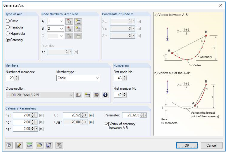
In addition to the numbers of members and the cross-section, the parameters of the catenary have to be defined. The heights here represent the distance from the nodes to the top of the catenary. The "parameter" corresponds to the radius of the curvature in the vertex. Any section of the catenary can thus be generated.
Shifting Nodes with RF-IMP/RSIMP
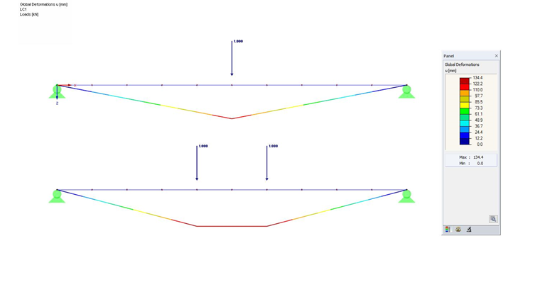
The cable geometry does not always correspond to the shape of the catenary. This is a rather unique case. In general, the cable geometry is related to the moment curve. A cable that is, for example, only loaded by a single load in the middle will form a triangular shape. If two single loads act on the cable, a trapezoidal shape will be the result.
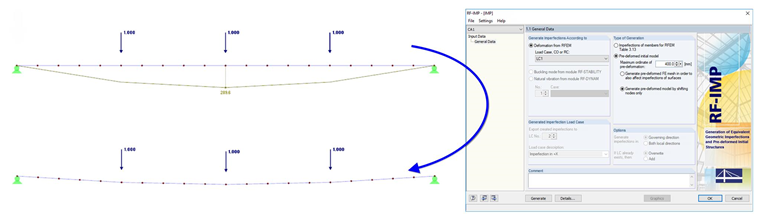
In case of arbitrary loading and thus also a more complex shape, the RF-IMP or RSIMP add-on module can be used here. By using this module, the cable geometry can be shifted anologously to the deformation. In doing this, a model can be generated relatively quickly, which approaches the shape sought.
Fine Tuning by Changing the Length
The methods shown above always define the initial state for the actual calculation. It will continue to deform due to the loads acting on the cable. Normally, however, the final state under load is predefined.
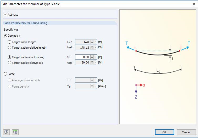
A certain sag will be exemplary under a defined load. The difficulty now is to define the initial shape, which results in the shape sought with the applied loading. Without using form-finding tools, this is often only possible iteratively. One solution approach might be to modify the initial state until the sag sought is found. Modeling the initial state again with the above-mentioned possibilities is an option, but due to the iterative process it is very cumbersome. Another option is to extend or shorten the cable with the "Axial strain" member load. The cable will be extended or shortened and superimposed with the other loads. If the state sought is not achieved, another calculation step can be performed by modifying the "axial strain" again. If the desired sag is achieved, the initial length of the cables ("Center of Gravity and Info" function) can be added with the modification of the lengths. The sum then corresponds to the unloaded cable length.
At this point, the COM interface has to be mentioned. A specifically defined optimization routine (for example, in Excel) could be linked with RFEM or RSTAB.
RF-FORM-FINDING
RFEM, with its RF-FORM-FINDING add-on module, offers the option to find a shape sought under a defined load automatically. It is only necessary to enter the member, the loading, and the parameters sought.
The initial shape and the member divisions do not have to be defined in detail. After the calculation, the module graphically displays the cable shape found, the forces, and the loaded and unloaded cable lengths.
Comparison
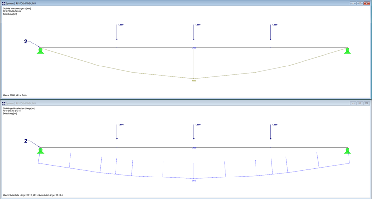
In the following text, the options will be compared with each other. The sag of 100 cm is required here for a cable with a bearing distance of 20 m under a defined loading. The manual option of a structure pre-deformed with RF-IMP (Structure 1) will be compared to the solution with RF-FORM-FINDING (Structure 2).
Structure 1: The cable has been pre-deformed 40 cm analogously to the deformation. Therefore, another deformation of 60 cm is required. The calculation results only in 6.1 cm. Therefore, the cable has to be extended. The related modification of the length has to be defined iteratively and results in 10.2 cm, which is uniformly distributed over all the members.
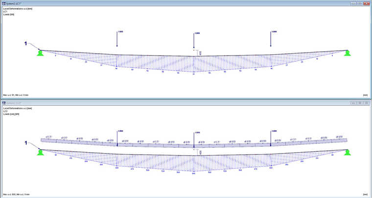
The resulting unloaded cable length corresponds to the sum of the length of the cables + the cable extension: (20.02 + 0.102) m = 20.122 m
Structure 2: Structure 2, where the form-finding is performed automatically in the background, calculates an unloaded cable length of 20.12 m, so that it results in a sag of 100 cm under the defined loading. This result is identical to the manually determined values. Less effort is needed here, since the initial shape has only been defined as a straight member and the whole iterative process is omitted.
Summary
When it comes to cable structures, RFEM and RSTAB offer different ways and means of designing them. The effort that might be required for a project should always be estimated. If more complex structures are designed, where the stiffnesses of the substructures are also included or an interaction between the cables takes place, the work will become uneconomical relatively quickly. In such cases, RFEM with its RF-FORM-FINDING add-on module offers a user-friendly and powerful solution.