


This article focuses mainly on determining the bearing resistance according to [1] Annex D and distinguishing between "drained" and "undrained" soil conditions.
Example: Hinged Column with Foundation Plate
A foundation plate for a hinged column will be designed to show the differences.
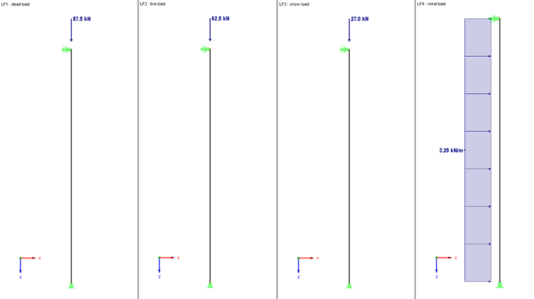
Self-weight, imposed load, snow, and wind are applied in four load cases to the column. The following graphic illustrates the load values.
The load combinations for the ultimate limit state design (STR/GEO) are generated automatically according to EN 1990 in RFEM and used for the designs in RF-/FOUNDATION Pro.
Input in RF/FOUNDATION Pro
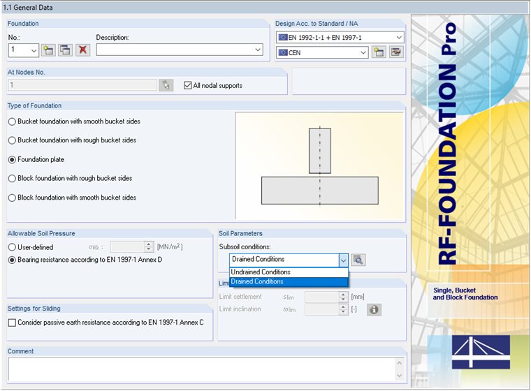
Since the bearing resistance for the foundation plate according to [1] Annex D will be determined, it is necessary to select this option in the "1.1 General Data" dialog box.
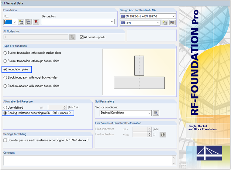
The dimensions of the foundation plate are defined with both a length and a width of 1.25 m, and a thickness t of 25 cm.

Additional specifications such as concrete grade, column dimensions, possible reinforcement diameters, reinforcement grade, and so on, are of no importance in this article, since only the bearing resistance and sliding design have been selected in the detail settings. The mentioned parameters are thus not part of the design and can be retained with the default settings.
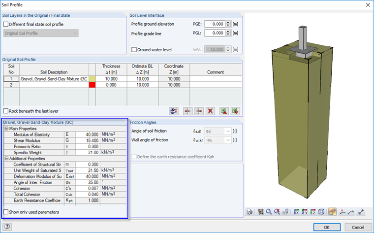
Presetting the soil parameters is crucial in determining the bearing resistance. This is possible with the "Soil Profile". In this regard, it is worth mentioning an earlier technical article that explains in detail how to enter the soil profile and determine the bearing resistance for layered soil with drained soil conditions.
In this case, the calculation is carried out with a constant soil parameter below the foundation base. The applied soil parameters are as follows:
- Gravel, Gravel-Sand-Clay Mixture (GC)
- γ = 21.0 kN/³
- φk = 35.0°
- c'k = 0.007 MN/m²
- cuk = 0.040 MN/m²
It is important to note that RF/FOUNDATION Pro only displays the parameters used by default. It depends on whether the "drained" or "undrained" subsoil conditions have been selected in the "1.1 General Data" dialog box. If "Show only used parameters" is not selected, all the parameters of the soil layer are displayed.
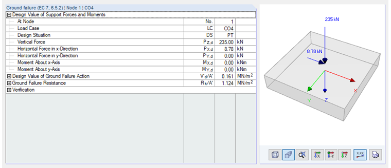
Governing Support Forces and Moments
The support forces of the generated CO4 govern for determining the bearing resistance. This load combination is defined as follows:
The resulting support forces are displayed in the graphic below.
"Drained" and "Undrained" Distinctions
The terms "consolidated" and "unconsolidated" can also be interpreted as "drained" and "undrained" in RF-/FOUNDATION Pro. Before starting the calculation, the user selects one of the two, which determines whether the bearing resistance is determined according to Equation (D.1) or (D.2).
In general, it is assumed that an increase of stress is absorbed or removed by the soil structure (drained state) in case of drained soil conditions. In case of undrained soil conditions, the increase of stress in the soil is not absorbed by the soil structure, but by the pore water, which is under overpressure (undrained state).
Bearing Resistance for Undrained Soil Conditions
The bearing resistance for undrained conditions results to, according to [1] Annex D, Eq. (D.1):
|
A' |
rechnerische Sohlfläche B' ⋅ L' |
|
cuk |
Gesamtkohäsion des undrainierten Bodens |
|
bc |
Faktor für die Sohlflächenneigung |
|
sc |
Formfaktoren der Sohlfläche |
|
ic |
Lastneigungsfaktor |
|
q |
Auflast in Höhe der Fundamentsohle |
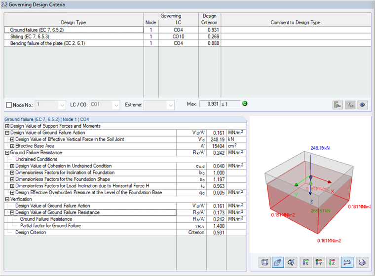
With the mentioned settings for the design, the following intermediate results arise:
- A' = 1.5404 m²
- bc = 1.00, since a horizontal position of the soil joint is always assumed in RF-FOUNDATION Pro
- sc = 1.197
- ic = 0.963
- q = 0.005 kN/m²
If this is inserted into (D.1), it results in a characteristic bearing resistance Rk/A' of:
The design value of the bearing resistance thus results in:
Bearing Resistance for Drained Soil Conditions
Since the determination of the bearing resistance for drained soil conditions was explained in an earlier article, Equation (D.2) is not repeated here.
Here, the bearing resistance for drained soil conditions results in:
Conclusion
The current example shows the influence of the selection of "drained" or "undrained" soil conditions in the 1.1 dialog box on the determination of the bearing resistance according to EN 1997-1 Annex D. In practice, drained soil conditions will be assumed in most cases.
Apart from this, RF-/FOUNDATION Pro provides a selection between the two approaches and offers the option to perform a case study with drained and undrained conditions if the soil conditions are unclear.
Besides the determination of the bearing resistance, the "drained" or "undrained" setting also has an influence on the design of the safety against sliding and the determination of the sliding resistance. More information is available under "Sliding" in Chapter 3 of the RF-FOUNDATION Pro manual.