


For rigid end plate connections that are predominantly subject to bending stress, it can be assumed that no (partial elliptical) distortion of the drilling occurs in the area of the bolts. For this reason, the drilling holes are often closed with rigid surfaces or by means of a spoked wheel (made of rigid members) for the modeling. The bolts are connected as beams, since mainly the axial stiffness is needed.
However, it is a different situation with shear/hole bearing connections. The force transmission takes place by a shear force of the bolt and a contact force acts on only a part of the drilling hole of the sheet. In the following text, the aim is to find a modeling approach for a centrically loaded sheet.
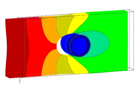
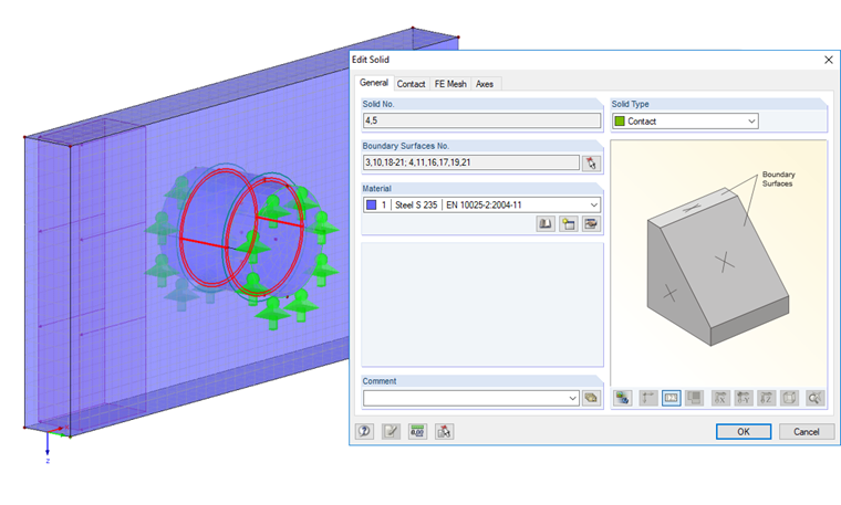
In the initial reference model, both the sheet and the bolt were displayed as a solid. For the non-linear contact problem between the bolt body and the inner drilling surface of the sheet, thin contact solids with failure under tension were defined.
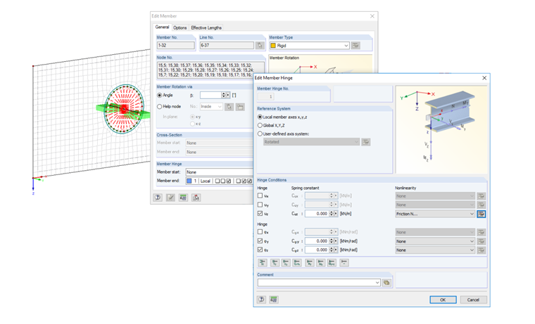
Comparison Model 1: Surface Model with a Spoked Wheel Made of Rigid Members
In its longitudinal axis, the bolt is represented by means of a beam, and the diameter by means of rigid members. It is important here to generate a slender spoked wheel to capture the change between pressure contact and gaping joint almost exactly. A moment hinge is assigned to the members at the drilling hole. The non-linear contact property is realized with the member nonlinearity "Failure under Tension". It is also possible to assign the nonlinearity "Fixed if negative N" to the local member hinge. So that the rigid members transfer as little load as possible by means of the shear force, and to ensure that the system remains stable, a friction coefficient (as with the solid model) of 0.01 is used.
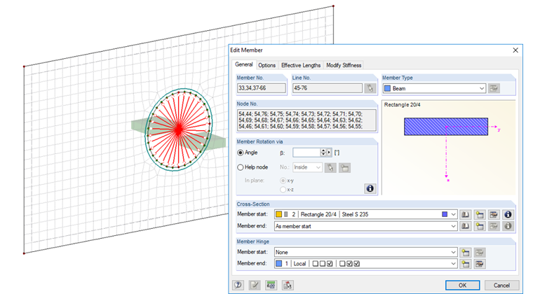
Comparison Model 2: Surface Model with a Spoked Wheel of Beams
Modeling is the same as with comparison model 1; the only difference is that the spoked wheel is designed with beams. In order to use almost correct stiffnesses, the dimensions of the member cross-section are assumed to be the surface thickness and the spacing of the members at the drilling hole.
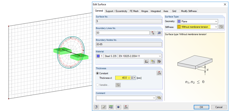
Comparison Model 3: Surface Model with Surface Type "Without Membrane Tension"
Instead of the spoked wheel, a surface is now applied. Since we have a relatively solid model here, the new area is assigned with twice the surface thickness. We choose the surface type with the "Without membrane tension" stiffness. Only compressive forces and moments can then be transferred. When membrane tensile forces occur, the corresponding FE elements fail.
Comparison Model 4: Surface Model with Line Release
The drilling is also closed by means of a surface for this model. For the non-linear force transmission, a line release with the nonlinearity "Fixed if vz Negative" is now used. A low friction is now assigned again to the other translational degrees of freedom.
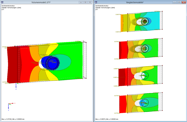
Comparison and Conclusion
We prefer to use the surface models instead of the solid model, because this means less modeling work as well as a much shorter calculation time.
When comparing the results, you will realize that, due to the overestimated stiffness, the first comparison model has the lowest deformations. Applying the approximate stiffnesses across the cross-sections as well as using the line release results in only slightly larger displacements than for the solid model.
The model with the "Without membrane tension" property has the largest deformations, but is the fastest modeling method. By default, when selecting this property, five load levels are used, which results in a longer calculation time.
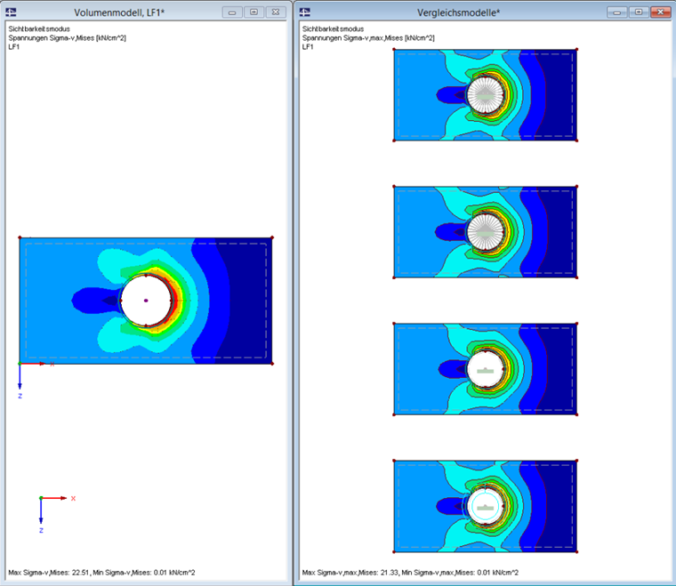
If you compare the equivalent stress of the four surface models, the stresses are almost the same and comparable to the solid stresses.
