


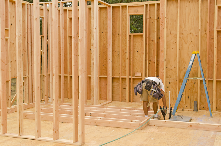
Timber Panel Structure
The ultimate limit state of a timber panel is determined according to standards such as Eurocode 5 or NDS 2018. In many countries, the shear panel theory is generally used for the design.
As mentioned in the beginning, the design of the timber panels is not the main focus of this analysis. Therefore, it is described in the following text only briefly according to the method regulated in Eurocode 5. Furthermore, these articles will not provide comprehensive information about the geometric rules or minimum distances of the fasteners.
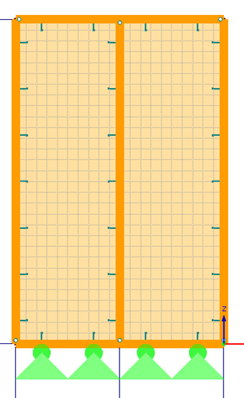
A timber panel wall consists of the following elements:
- Head rib
- Inner rib, if applicable
- Cladding
- Fasteners
- Edge rib
- Foot rib
Ultimate Limit State
The cladding consisting of OSB is usually connected with the ribs by means of staples.
Ultimate limit state of a fastener:
Equation 1:
Yield moment My,Rk = 150 ⋅ d3
Equation 2:
Hole bearing resistance fh,1,k = 65 ⋅ d-0.7 ⋅ t0.1
;fh,2,k = 0.082⋅ρk ⋅ d-0.3
Equation 3:
Load-bearing capacity (NA.109 DIN EN 1995-1-1)
where
d is the diameter of the fastener,
t is the cladding thickness.
Equation 4:
Wall width ratio
Equation 5:
Strength limit state
where
bi is the total wall width,
h is the wall height.
b0 is
av is a distance of the fastener.
Further important designs include, for example, the buckling analysis of the edge ribs, the design of the anchorage, and the buckling design of the cladding.
Deformation
Equivalent to the ultimate limit state design, the four elements of a timber panel are important in calculating the deformation when determining the stiffness:
- Flexibility of the fastener
- Flexibility of the cladding
- Yielding of the ribs
- Flexibility of the anchorage
Equation 6:
Yielding of fastener (clamping)
Equation 7:
Yielding of cladding
Equation 8:
Yielding of the ribs
Conclusion
This article describes the determination of the ultimate limit state and the stiffness of a timber panel. In the following articles about timber panels, these basics will be used to describe the consideration of these stiffnesses in a two- or three-dimensional calculation.