


This article demonstrates the use of the "Parametric-Thin-Walled" cross-section available in RFEM based on the LRFD example shown in AISC Design Guide 15: Rehabilitation and Retrofit [2]. The RF-STEEL AISC add-on module is used to perform the design check for both the unreinforced and reinforced columns according to AISC Chapter E.
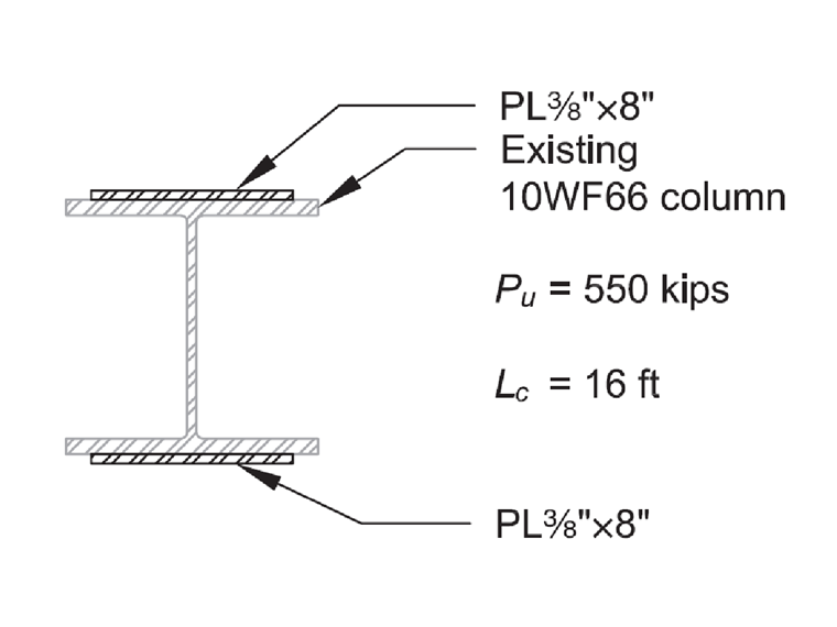
Shown below is example 6.2 of AISC Design Guide 15 [2], where the AISC historic shape W10X66 (Fy = 33 ksi) is used for the 16-foot-long column.
The following steps outline the procedure of creating a user-defined cross-section and material.
Creating User-Defined W10X66 Cross-Section
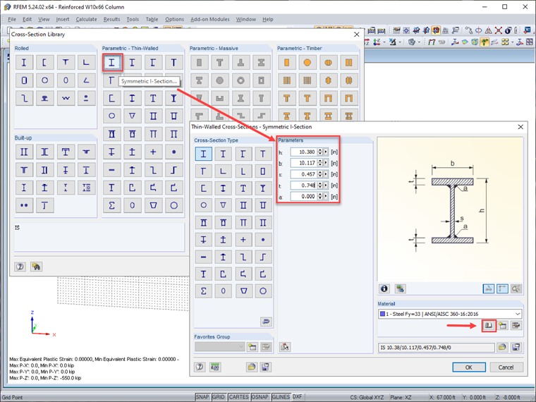
- Choose the "Symmetric I-Section" in the Cross-Section Library. Then enter the geometric properties found on Table 5-2.1 (page 50 of Design Guide 15 [2]). The next step is to create a new user-defined material for Fy = 33 ksi steel using the [Import Material from Material Library] button.
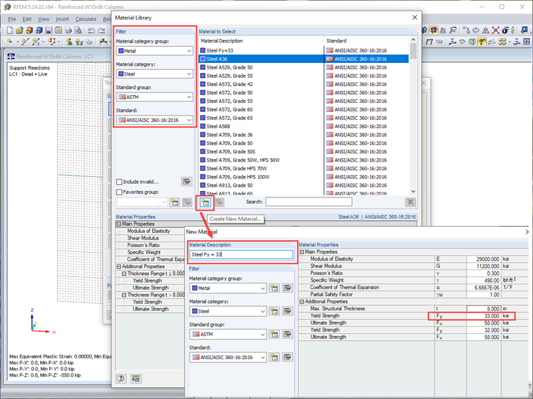
- Fill out the filter in the Material Library, then "Create New Material" based on "Steel A36". In the next window, fill in the "Material Description" and revise Fy to 33 ksi.
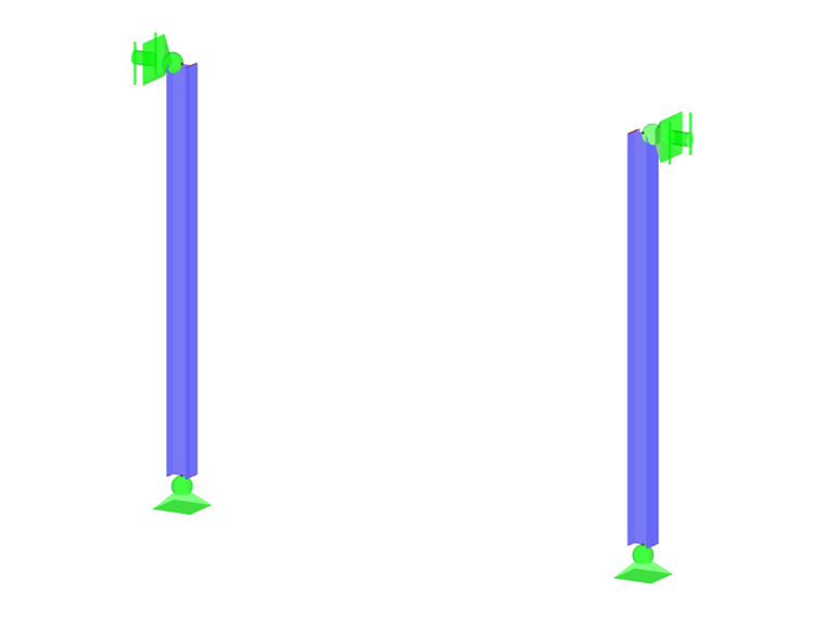
- Draw the 16-foot-long member. Provide pinned support (Z-rotation fixed) at the bottom of the column. For the support at the top, only translation is fixed in the X and Y directions. Apply axial load = 550 kips (Dead + Live).
- Solve the model using the add-on module RF-STEEL AISC.
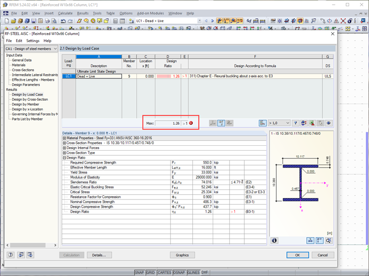
As shown above, the required strength exceeds the available strength by 26%, and therefore the column requires reinforcing steel plates (Fy = 36 ksi) welded to the column flanges. Assume that the reinforcing plates are installed over the entire column length.
Note: The minor discrepancies in compressive strength between the RFEM model and AISC hand-calculation example [2] are due to the difference in cross-sectional areas (a corner radius is not included in the RFEM cross-section).
Creating User-Defined Reinforced W10X66 Column with A36 Steel Plates
The welded reinforcing plates will increase both the area and the moment of inertia of the column. This will result in an increased compressive strength as determined from AISC Specification Section E3 [1].
The design of reinforcement is an iterative process best done using a spreadsheet. This solution will present only the final solution, where two 3/8-inch-thick x 8-inch-wide cover plates are welded to the column flanges as shown below.
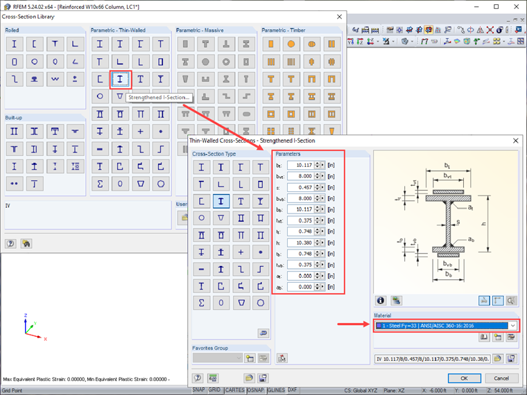
- Choose the "Strengthened I-Section" in the Cross-Section Library. Then enter the geometric properties of the W10x66 column and the 3/8 inch x 8 inch reinforcement plates. Pick the same user-defined material "Steel Fy=33" that was previously created (per AISC Design Guide 15 [2], "The existing column has a yield strength of Fy = 33 ksi, while the reinforcing plates have a yield strength of Fy = 36 ksi. For the calculation of the available compressive strength of the column, conservatively consider a yield strength of 33 ksi for the entire reinforced column cross-section.").
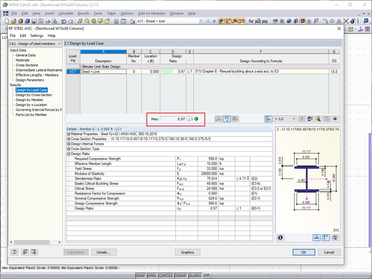
- Repeat the same procedure of drawing the column and applying loads as shown previously. Solve the model using RF-STEEL AISC. As shown below, the reinforced column meets the design code check.
Checking Requirements for Built-up Columns as per AISC Section E6 and Designing Welds
From AISC Specification Section E6.1 [1], the connections at the ends of the reinforcing plates are designed for the full compressive load in the plate. Design the end connections for the yield strength of the reinforcing plates.
Use 1/4 inch fillet welds on both sides of the reinforcing plate. The flange thickness is tf = 0.748 inch and the reinforcing plate is 3/8 inch thick, thus the weld size meets the minimum size requirements of AISC Specification Table J2.4 [1]. The required weld length is:
|
lweld |
Length of weld |
|
Pu |
Compressive load of (1) plate = Fy . Ag |
|
Fy |
Yield strength of plate = 36 ksi |
|
Ag |
Gross area of (1) plate = 0.375 in x 8.0 in = 3.0 in2 |
|
ΦRn |
Weld design strength per inch of weld |
This weld length meets the prescriptive requirement from AISC section E6.2(b) [1] that the end weld length not be less than the maximum width of the member.
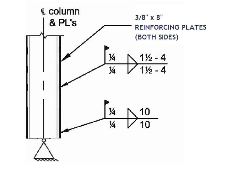
Use 1/4" weld x 10-inch-long longitudinal welds on both sides at the ends of the plates.
From AISC Section E6.1(b) [1], a modified slenderness ratio for built-up columns is required when a/ri > 40, where a is the distance between welds. To avoid the need to use a modified slenderness, the maximum distance between intermittent fillet welds should be limited to:
|
ri |
Radius of gyration of (1) plate |
|
Ixi |
bt3/12 = [(8.0in) . (0.375in)3]/12 =0.0352in4 (one plate) |
|
Ai |
Area of (1) plate = t w = (0.375in)(8in) = 3.0in2 |
|
amax |
Maximum distance between the intermittent fillet welds |
Use intermittent connecting welds 1.5 inch long at 4 inches on center (Section J2.2b for minimum weld length). A 1.5-inch-long weld meets the 4*weld size and 1.5 inch minimum.
From AISC section E6.2(a) [1], the individual components of compression members must be connected at intervals, a, such that the slenderness ratio, a/ri, does not exceed 3/4 times the governing slenderness ratio of the built-up member.
|
a |
Weld intervals |
|
ri |
Radius of gyration of (1) plate |
|
Lc |
Unbraced length of the column = 16 ft = 192 in |
|
ro |
Minimum radius of gyration of the reinforced section (rz in RFEM) |
From AISC section E6.2(b) [1], the maximum spacing of intermittent welds shall not exceed the plate thickness times 0.75 √(E/Fy), nor 12 inches.
|
t |
Plate thickness |
|
E |
Modulus of elasticity |
|
Fy |
Yield strength of the reinforced section |
The final design of the reinforced column is shown below.
As shown from the above example, the RFEM "Parametric Thin-Walled" cross-section can be utilized to calculate the geometric properties of commonly used built-up members. The add-on module RF-STEEL AISC calculates the member's design strengths and performs code check.