


Introduction
The enveloping design internal forces take into account the possible internal force distributions along the wall height resulting from plastic redistributions and higher vibration modes. The goal is to apply those internal forces that may result from the development of plastic hinges and the formation of the intended ductile failure mechanism.
This ensures that non-dissipative areas, that is, areas where no targeted plastic energy conversion is intended, and brittle failure modes are avoided, and that the structural system can reliably absorb the energy dissipation processes intended in the ductile design concept.
Further information is provided in the manual chapter linked below.
Determination of Seismic Loads
The internal forces are generally calculated using the linear response spectrum analysis ([1], Section 4.3.3.3), where the internal forces are calculated separately for each vibration mode and then superimposed according to SRSS or the CQC rule.
The procedure can be followed in detail in the article on the response spectrum analysis and simplified seismic analyses.
Enveloping Design Internal Forces
For ductile walls, the bending moment and shear force should not be taken directly from the response spectrum analysis. Instead, EC8-1 uses the analysis results to construct an enveloping distribution over the wall height, which is intended to ensure that the plastic hinge occurs exclusively at the base of the wall and that the wall does not fail due to shear. For the bending moment, this is achieved using a tensile force shift rule; for the shear force, it is achieved using an amplification factor that takes into account the overstrength of the bending reinforcement and the effect of higher vibration modes.
The following section shows step by step how the envelopes are determined, using a bracing wall as an example.
Subject of Analysis
Description of Structural System
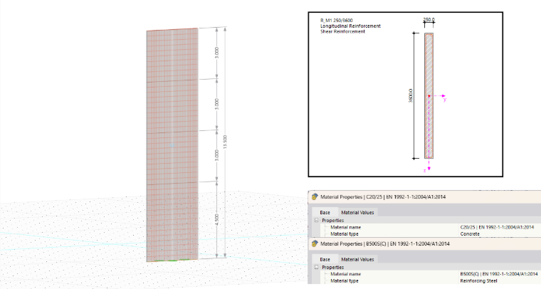
A four-story bracing wall classified as ductility class DCM is considered, so that ε = 1.5 applies regardless of the slenderness ratio; with Hw/lw = 3.75, the wall would be classified as slender based on the slenderness criterion in any case. The materials used are C20/25 concrete and B500S(C) reinforcing steel. Two sections are considered—the wall base (x = 0.000 m) and a section at x = 3.375 m—for the exemplary applied seismic load combinations CO2 and CO4.
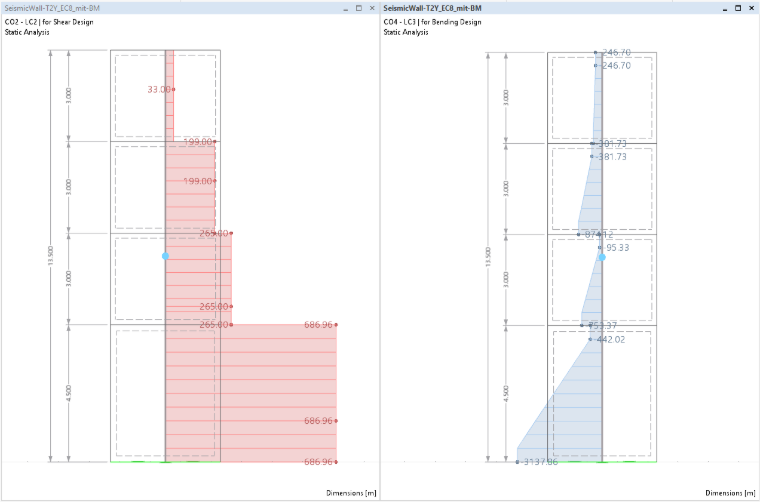
The following image shows the internal force distributions for Vz and My resulting from the loads.
Moment Envelopes in Example
The purpose of the moment envelopes is to prevent unwanted plasticization in the wall shaft and to ensure that the plastic hinge only occurs at the wall base. The structure is designed according to [1], 5.4.2.4(5) (DCM) or 5.5.2.4.1(5) (DCH) in conjunction with 5.4.2.4(8), Figure 5.4, and is carried out step by step below for the wall from the structural description.
Step 1: Design Moments
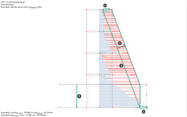
The starting point is the moments resulting from the seismic loads at both ends of the wall. The analysis results in
- (x = 0) M'Ed,0 = 3,137.86 kNm at the wall base, and
- (x = Hw) M'Ed,Hw = 246.70 kNm at the wall head.
Step 2: Linear Envelopes
Next, the straight line connecting the design moment at the base of the wall to the design moment at the wall head over the entire wall height Hw is determined. Its slope is:
- tan φM = (M'Ed,0 − M'Ed,Hw) / Hw
Using the values for the considered wall:
- tan φ M = (3,137.86 − 246.70) kNm / 13.50 m = 214.16 kN
Step 3: Shift Rule
The moment envelope has to be shifted vertically according to the shift rule a l, which can be determined according to [2], 9.2.1.3(2), Eq. (9.2).
- al = (z / 2) · (cot θz − cot α)
Here, z is the internal lever arm, θz is the slope of the concrete compression strut, and α is the slope of the shear reinforcement towards the member axis. For the considered wall, the shear design results in z = 2,556.3 mm, θz = 21.80°, and α = 90° (vertical stirrups), which gives:
- al = (2,556.3 mm / 2) · (cot 21.80° − cot 90°) = 3.195 m
Step 4: Bilinear Moment Envelope
If this line is shifted by a l toward the wall head, the final, bilinear moment envelope is determined as follows according to [1], 5.4.2.4(8), Image 5.4.
\[
M_{Ed}(x) =
\begin{cases}
|M'_{Ed,0}| & \text{for } 0 \le x \le a_l \\[4pt]
|M'_{Ed,0}| - \tan\varphi_M \cdot (x - a_l) & \text{for } a_l < x \le H_w
\end{cases}
\]
Simply put, this means: Over the range 0 ≤ x ≤ al, the design moment remains constant at |M'Ed,0|; above al, it decreases linearly with the slope tan φM up to the wall head.
For the example wall, this means: The section at the wall base (x = 0.000 m) lies within al = 3.195 m, so the full design moment is to be applied:
- MEd = |M'Ed,0| = 3,137.86 kNm.
Above this point, the distribution of the design moment can be described by the following equation of a degree.
- MEd = |M'Ed,0| − tan φM · (x − al) = 3,137.86 kN·m − 214.16 kN · (x − 3.195 m)
For the section at x = 3.375 m, which lies above al, the result is:
- MEd = 3,137.86 kNm − 214.16 kN · (3.375 m − 3.195 m) = 3,099.31 kNm
The image below shows the moment distribution initially resulting from the loads (blue), with the labeled calculation steps and the final resulting distribution of the enveloping design moment (red).
Shear Force Envelope in Example
The shear force design of ductile walls is particularly critical, since shear failure is brittle rather than ductile—premature shear failure would prevent the intended dissipative behavior at the wall base. EC8-1 therefore prescribes a significant increase in the design seismic lateral forces ([1], 5.4.2.4(7) for DCM or 5.5.2.4.1(7) for DCH), which takes into account the influence of higher vibration modes and the overstrength of the flexural reinforcement. This procedure is also calculated directly for the example wall below.
Step 1: Design Shear Forces
The analysis results in
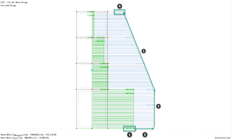
- V'Ed,0 = 686.95 kN at the wall base, and
- V'Ed,Hw = 32.86 kN at the wall head.
Step 2: Factorization with Magnification Factor
These values are multiplied by a magnification factor ε:
- VEd = ε · V'Ed.
This factor depends on the ductility class and—for DCH—additionally on the wall slenderness ratio Hw/ Lw. It includes the overstrength factor γRd, which reflects the variation between the actual and design yield strength of the flexural reinforcement (γRd = 1.0 for DCM, γRd = 1.2 for DCH):
| Case | Amplification Factor ε |
| DCM (compact and slender) | ε = 1.5 |
| DCH, compact (Hw/Lw < 2.0) | ε = γRd · (MRd / MEd) ≤ q |
| DCH, slender (Hw / Lw > 2.0) | ε = q · √[ (γRd / q · MRd / MEd)² + 0.1 · (Se(Tc) / Sd(T1))² ] ≤ q |
The considered wall is assigned to ductility class DCM, so that ε = 1.5 applies regardless of the slenderness ratio. Thus, the reinforced design value at the wall base is:
- VEd,0 = ε · V'Ed,0 = 1.5 · 686.95 kN = 1,030.43 kN
For compact walls, the envelope is thus already fully described, since the shear force remains constant over the entire wall height.
Step 3: Design Shear Force Up to Hw/3
For slender walls—as in this example, since Hw/lw = 3.75 > 2.0—it is also necessary to determine the distribution over height:
Up to a height of H w /3, the reinforced shear force V Ed,0 is maintained.
Step 4: Design Shear Force at Wall Head
At the wall head, the design shear force is subject to a limitation ([1], 5.4.2.4(8)):
- VEd,Hw = max{ ε · V'Ed,Hw ; VEd,0 / 2 }
The limitation to half the value at the wall base prevents an excessive, unrealistic shear force at the wall head, where there is no plastic hinge zone. For the example wall, this results in:
- VEd,Hw = max{ 1.5 · 32.86 kN; 1,030.43 kN / 2} = max{ 49.28 kN; 515.21 kN } = 515.21 kN
The governing limitation here is therefore the limitation to half the design value at the wall base, not the reinforced value at the wall head itself.
Step 5: Linear Distribution to Wall Head
Linear interpolation is performed between the height $H < sub > w < /sub > / 3$ and the wall head ([1], 5.4.2.4(8), Figure 5.4):
- VEd(x) = (3/2) · (VEd,Hw − VEd,Hw/3) / Hw · x − (1/2) · (VEd,Hw − 3 · VEd,Hw/3)
However, this interpolation is not required for the two sections of the example wall that are analyzed:
Since Hw/3 = 4.50 m, and both the wall base (0.000 m) and the section at x = 3.375 m lie below this threshold, the shear force envelope remains constant at that point, equal to the reinforced wall base value:
- VEd(x) = VEd,0 = 1,030.43 kN
The image below shows the shear force distribution initially derived from the loads (green), with the labeled calculation steps and the resulting envelope of the design shear force (blue).
Summary
The determination of the enveloping design internal forces for bracing walls according to standards is handled efficiently and in compliance with the standards by the Concrete Design add-on in RFEM 6: The envelope for the design moments and shear forces—including tensile force offset, factor γRd, and dynamic shear force amplification with factor ε—is calculated automatically based on the specified wall parameters and ductility class.