


Hand calculations, spreadsheets, and linear finite element software cannot accurately capture this nonlinear behavior. Nails slip and eventually yield before the sheathing or framing reaches capacity, which influences a significant portion of the shear wall’s stiffness and deflection.
With RFEM 6’s nonlinear capabilities, the model automatically generates a nonlinear line hinge between the sheathing surface and the framing members based on the fastener load-slip behavior in the 2021 SDPWS. Fastener design is the subsequent step carried out in the Timber Design add-on to ensure adequate shear wall stud-to-sheathing capacity.
The SDPWS Fastener Slip Equation
Table C4.2.3D [1] gives the load-slip relationship for common nail sizes (6d, 8d, 10d) in wood structural panel sheathing. For each size, the table provides:
- A maximum fastener load, Vₙ (lb/fastener), where the fastener begins to yield
- A slip equation, eₙ, as a function of fastener load
The exponents fastener slip equations mean the connection stiffens and softens nonlinearly as it approaches yield. This ductile behavior for shear walls is needed for lateral events such as seismic or wind.
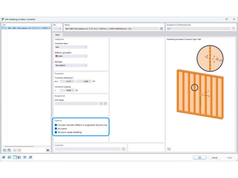
Referencing the SDPWS, this slip behavior is only addressed along the stud length in the longitudinal direction. The nonlinear slip can be applied in the transverse direction as well, but this is not specifically mentioned in the code. There is also a separate equation for fasteners installed in green lumber vs. dry lumber as well as a 20% increase in slip for non-structural grade sheathing. These optional settings are included in RFEM 6 when defining the shear wall sheathing-to-beam connectors as shown in the image below.
Verification of the RFEM 6 Load-Slip Curve
It’s assumed that a wood shear wall modeled in RFEM 6 includes 8d common nail at 6-inch spacing (2 fasteners/ft), structural I-grade sheathing, and dry lumber. Referencing Table C4.2.3D [1], the maximum yield load is 220 lb/fastener and the slip equation for dry lumber is:
eₙ = (Vₙ/616)3.018 (in)
RFEM 6 generates an automatic nonlinear line hinge between the studs and sheathing with 10 intermediate points, as shown in the image below.
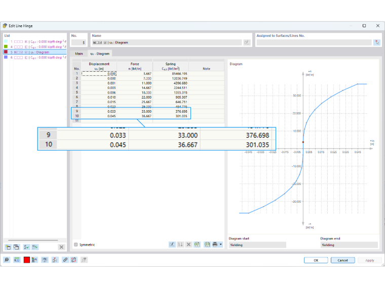
The coordinates and slope of diagram points 9 and 10 are further verified to ensure the Table C4.2.3D [1] fastener slip equation application.
Point 10 distributed force (n) at 220 lb/fastener (yield):
n₂₂₀ = (220 lb/fastener)(2 fastener/ft)(1 ft/12 in) = 36.667 lb/in
Point 10 corresponding slip (u):
uₓ,₂₂₀ = (220/616)3.018 = 0.0447 in
Point 9 distributed force (n) at 198 lb/fastener (90% of yield):
n₁₉₈ = (198 lb/fastener)(2 fastener/ft)(1 ft/12 in) = 33.0 lb/in
Point 9 corresponding slip (u):
uₓ,₁₉₈ = (198/616)3.018 = 0.0325 in
Slope (spring stiffness) between Points 9 and 10:
Cᵤ,ₓ = (36.667 − 33.0)/(0.0447 − 0.0325) ≈ 301 lb/in²
These same calculations are applied along the multi-point load-slip curve from Table C4.2.3D [1] directly. The model captures the connection's nonlinear behavior across the load range. This replaces the manual approach, where nail slip is either ignored, considered linear, or applied as one empirical deflection term at the end of a hand calc with no visibility into how stiffness changes with load or how slip redistributes force between panels.
Nominal Unit Shear Capacity Fastener Design
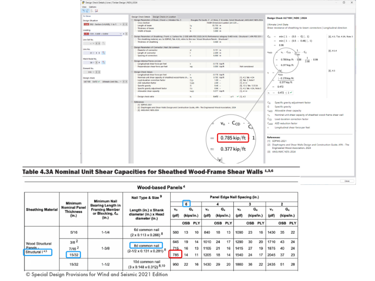
The nonlinear fastener slip directly influences the shear wall analysis in RFEM 6. Fastener design is the subsequent step carried out in the Timber Design add-on. The design provisions from the 2021 SDPWS Table 4.3A provide the nominal capacity (vₙ) influenced by:
- Sheathing material and minimum nominal thickness (5/16 in, 3/8 in, 7/16 in, 15/32 in, etc.)
- Fastener type and size (6d, 8d, 10d common nail)
- Panel edge nail spacing (6, 4, 3, or 2 in)
A shear wall modeled in RFEM 6 allows input of the above variables that may fall outside the given table values. Therefore, the following assumptions are applied in the Timber Design add-on for these scenarios:
- Panel thickness less than the table minimum is a design error. Thickness greater than the table value rounds down with no added capacity assumed (e.g., 19/32 in references 15/32 in row).
- Nail spacing is tabulated only at 6, 4, 3, and 2 in. A spacing between values rounds down to the more conservative value (e.g., 3.5 in references 3 in). Greater than 6 in is a design error; less than 2 in is capped at the 2 in. row.
Table footnotes that modify capacities for specific framing species, panel grade, and other conditions, are automatically considered in the fastener design.
The full fastener design is reported under Design Check UL7100, as shown below. The allowable shear vs. demand is given as design ratio with detailed design check equations, code references, and transparent data output.
From Manual Checks to FEA-Based Design
The load-slip curve and the capacity design checks close a loop that used to take separate hand calculations at each step or required less accurate linear assumptions. The RFEM 6 nonlinear line hinge governs how the model deforms under load, capturing panel nail slip as one of the four SDPWS deflection sources. The Timber Design add-on independently checks connector strength against the shear demand at all fastener locations to ensure a safe and accurate design.
For more information on this topic, refer to the webinar | 2024 NDS / 2021 SDPWS Timber Shear Wall Design in RFEM 6 linked below.