9 Results
View Results:
Sort by:

A member's boundary conditions decisively influence the elastic critical moment for lateral-torsional buckling Mcr. The program uses a planar model with four degrees of freedom for its determination. The corresponding coefficients kz and kw can be defined individually for standard-compliant cross-sections. This allows you to describe the degrees of freedom available at both member ends due to the support conditions.

The individually defined printout reports in an RFEM or RSTAB model can be displayed in different ways.
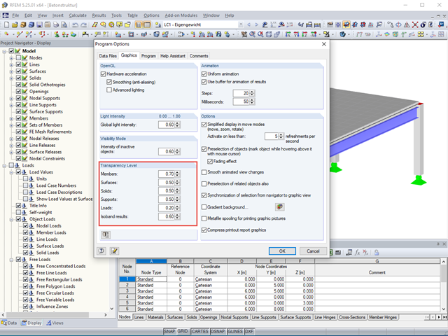
The transparency intensity of various graphic elements in the Solid Transparent Display Mode can be edited individually in the Program Options dialog box under the Graphic tab to improve the overview.

RFEM offers the following options to design a pinned end plate connection. First, there is the option in RF-JOINTS Steel - Pinned to enter the corresponding parameters quickly and easily to receive a documented analysis, including graphics. It is also possible to model such a connection individually in RFEM and then to evaluate or manually design the results. In the following example, the particularities of this modeling will be explained and the shear forces of the bolts will be compared to the corresponding results from RF-JOINTS Steel - Pinned.
.png?mw=640&hash=5852c5c8a1cdb9f021a168d75c0a0466fb430ef7)
Lattice towers represent typical applications in steel construction. Examples of this special type of truss structure are antenna and overhead line towers, as well as columns for wind power stations, cable cars, and supporting frame constructions. The modeling can be done individually in RFEM and RSTAB by entering various tower elements. Furthermore, you can use different copy functions and parameterized input options. However, this procedure normally requires considerable effort. It is more convenient to model such structures using prefabricated catalog elements provided by the Block Manager. These elements are automatically stored in the database during program installation. Thus, you can use tower segments, platforms, antenna brackets, cable ducts, and so on as parameterized building blocks for generating diverse tower structures.
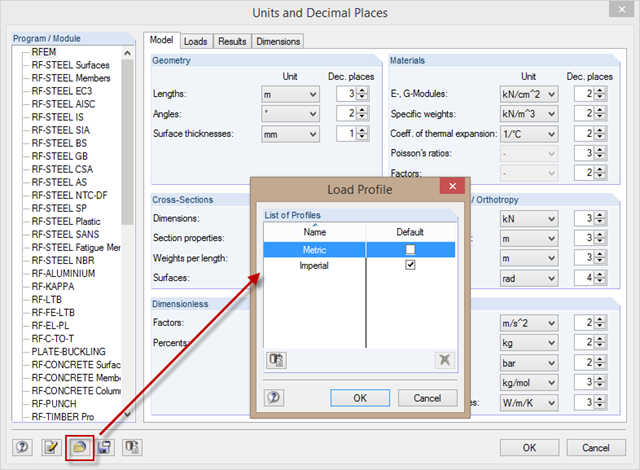
When changing the units from the metric to the imperial measurement system, it is not necessary to change all the units individually. To do this, corresponding unit profiles are available in the "Units and Decimal Places" dialog box, which you can activate as shown in the picture.
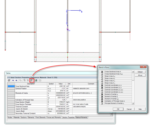
The result window of the cross-section properties can be adjusted individually using the [Filter] button in the table menu bar. You can then activate or deactivate the individual cross-section parameters in the dialog box.
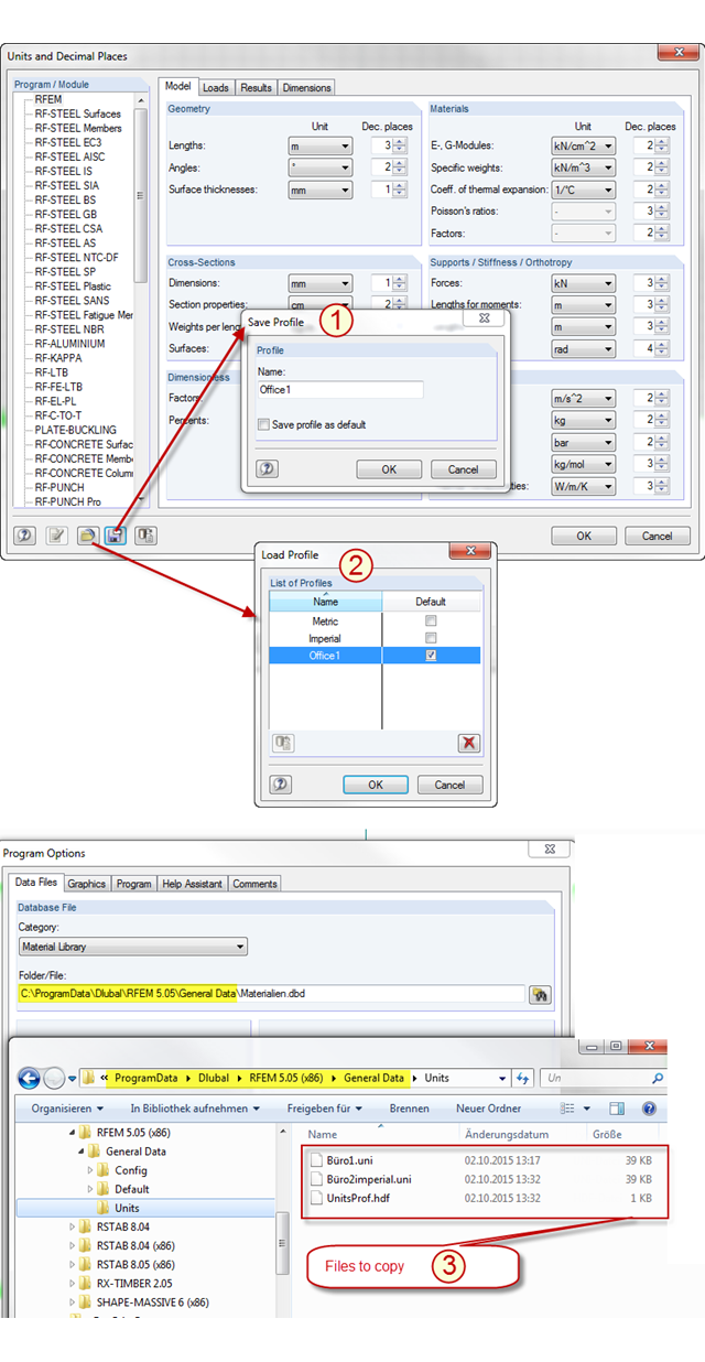
In RFEM and RSTAB, there are two predefined unit profiles available by default. These profiles cover the metric and the imperial systems of measurement. You can individually adjust the units predefined by Dlubal Software, including the decimal places used. To avoid losing the changes you have made, you can save a new profile for the units (see Item [1] in the picture). The stored profile can be loaded again (see Item [2] in the picture) or transferred from PC to PC. To do this, simply copy the content of the "Units" folder in the RFEM or RSTAB file directory from one PC to another (see Item [3] in the picture). In this way, you can achieve an office standard regarding the units used in all your workplaces.
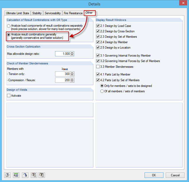
You can obtain many load combinations, especially when using the automatic generation of combinations. These are automatically combined in a result combination (RC) with the OR operator as an envelope. Then, if you select one RC for design in RF‑/STEEL EC3, it may lead to a very long calculation time because the module calculates all combination options individually by default, then displays the results of the governing combination.