18 Results
View Results:
Sort by:

The add-on modules for designing structural member components according to national, European, and international standards also show design results in addition to numerical output in tables graphically, as diagrams displayed on the framework.

For line supports, there is an option to graphically display the additional information for all directions.
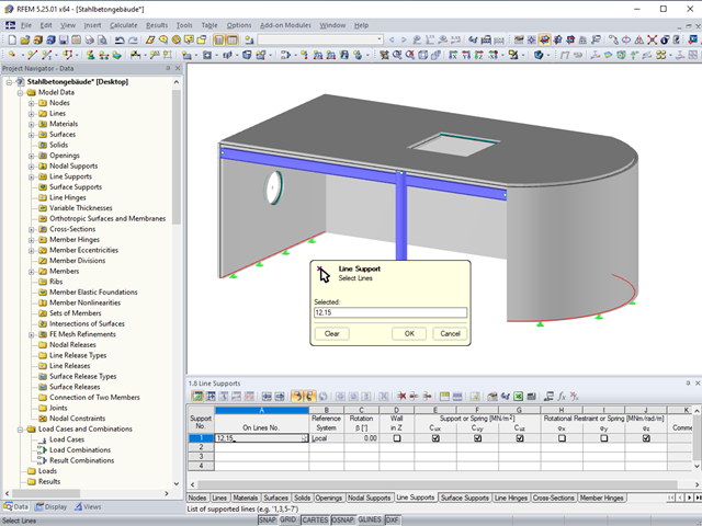
In the tables of RFEM 5 and RSTAB 8, you can select the list of objects graphically by using the mouse.
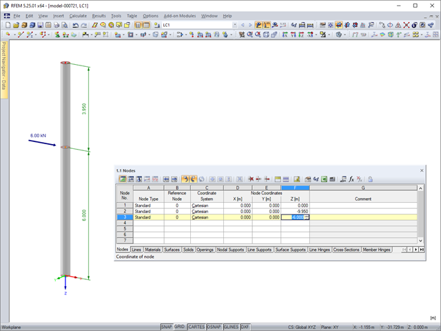
Model and load objects can be defined graphically or in tables, or they can be created using parameters (see the manual). With this parameterized input, you can also access the cells of certain tables of the program. In this way, it is possible to link a load parameter with a model data parameter, for example. The reference is created by the $ sign.
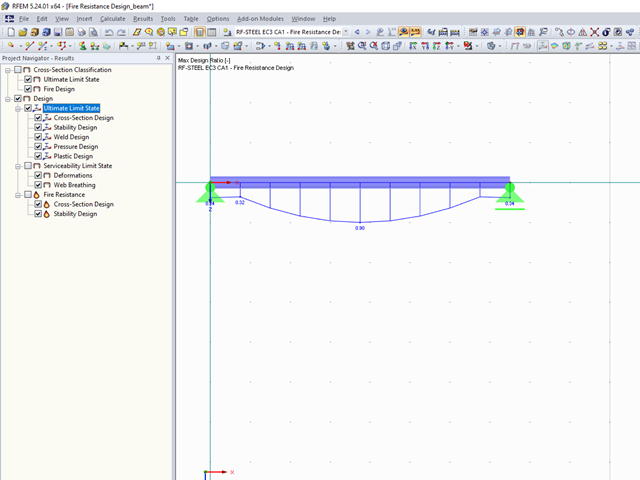
The final results of the designs of members and sets of members in the RF‑/STEEL EC3 add-on module can be displayed graphically in the work window of RFEM and RSTAB. By selecting the corresponding design case in the load case menu, the results contained in it are displayed.
An effective way to represent reinforcement graphically is to arrange it in groups.

After running an analysis in RF-/STEEL AISC, the mode shapes for sets of members can be viewed graphically in a separate window. Select the relevant set of members in the result window and click the [Mode Shapes] button.
![Time-Dependent Settlement Components [2]](/en/webimage/009673/2419908/01-en-png-png.png?mw=640&hash=5e657e3feb5c1bb6d21727468dd85d91e1c9f29f)
For the serviceability limit state design according to Section 6.6 of Eurocode EN 1997‑1, settlement has to be calculated for spread foundations. RF-/FOUNDATION Pro allows you to perform the settlement calculation for a single foundation. For this, you can chose between an elastic and a solid foundation. By defining a soil profile, it is possible to consider several soil layers under the foundation base. The results of the settlement, foundation tilting, and vertical soil contact stress distribution are displayed graphically and in tables to provide a quick and clear overview of the calculation performed. In addition to the design of the foundation settlement in RF-/FOUNDATION Pro, the structural analysis determines the representative spring constants for the support and can be exported to the structural model of RFEM or RSTAB.
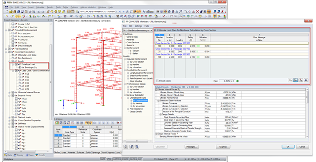
With RFEM 5.6.1103 and RSTAB 8.6.1103, there is an improved result output for the nonlinear calculation of reinforced concrete design in RF‑CONCRETE Members and CONCRETE. The new result windows include tables with a wide range of loading results; for example, governing load with the maximum ratio. In addition, you can now display the envelope results for the maximum ratio graphically.
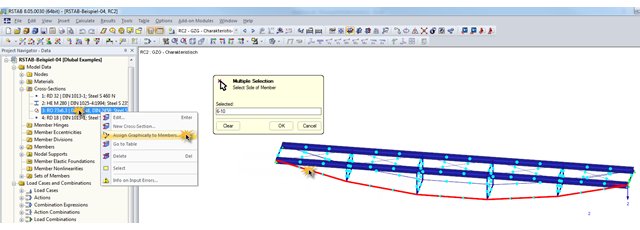
During the optimization of a structure, the individual cross‑sections may have to be modified several times. This can be done very quickly using the function "Assign Graphically to Members", which is available under "Cross‑Sections" in Project Navigator – Data.
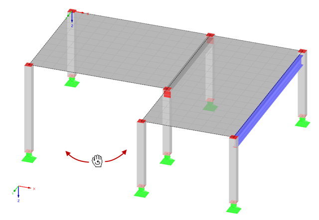
Rotating in the work window is one of the most important functions allowing you to enter a model graphically in RFEM or RSTAB.
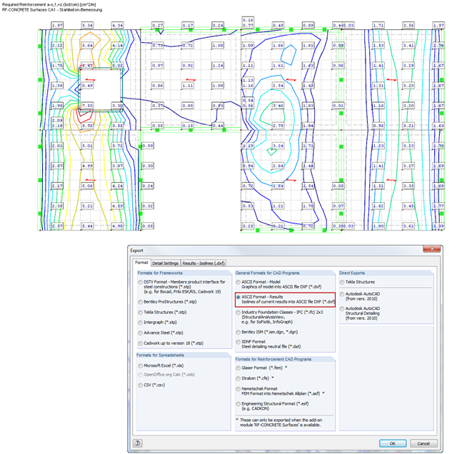
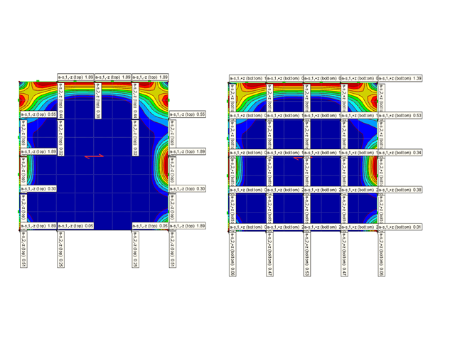
RF‑CONCRETE Surfaces performs the ultimate and the serviceability limit state design of slabs, plates, folded plates, and shells. In RFEM 5, the reinforcement resulting from this design can be displayed graphically on the surfaces of the structure using isolines. For the reinforcement design, it may be useful to export the results as isoline distribution in a DXF file in order to open them in a CAD application as background layers.
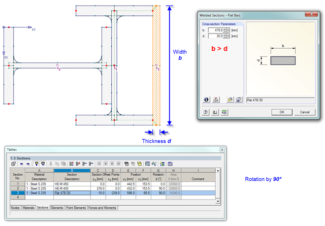
The SHAPE‑THIN cross‑section properties program provides convenient options for graphically setting the section reinforcements. When modeling flat bar extensions, you should note one rule only: The length of the element must be greater than the width.
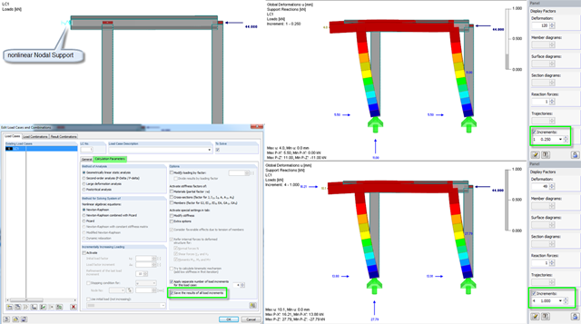
In RFEM, you can save the results of individual load increments during the calculation and display them graphically. Thus, you can graphically display and check the reaction diagram of different load levels for nonlinear supports.
In RFEM, you can save the results of individual load increments during the calculation and display them graphically. Thus, you can graphically display and check the reaction diagram of different load levels for nonlinear supports.
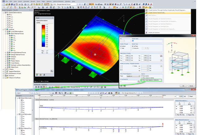
For evaluating results on surfaces, RFEM provides the option to define sections. Basically, two different types of sections are available. One, the creation of a temporary section showing the result diagrams of the desired cutting edge only once; the other, the definition of a section in the dialog box, which is then created as a separate object in RFEM, and thus the results can be viewed at any time. Displaying the results of defined sections is done graphically in RFEM, but they can also be displayed separately in a dialog box and be included in the printout report.
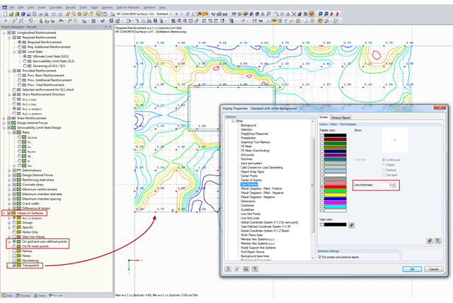
You can document the results of RF‑CONCRETE Surfaces graphically in the printout report. To do this, the "Values on Surfaces" setting is often selected in the Results Navigator of RF‑CONCRETE Surfaces. A text bubble including a result value is displayed, and depending on the settings in the Results Navigator, it can be displayed on the surface grid points, manually defined points, or in FE mesh points.
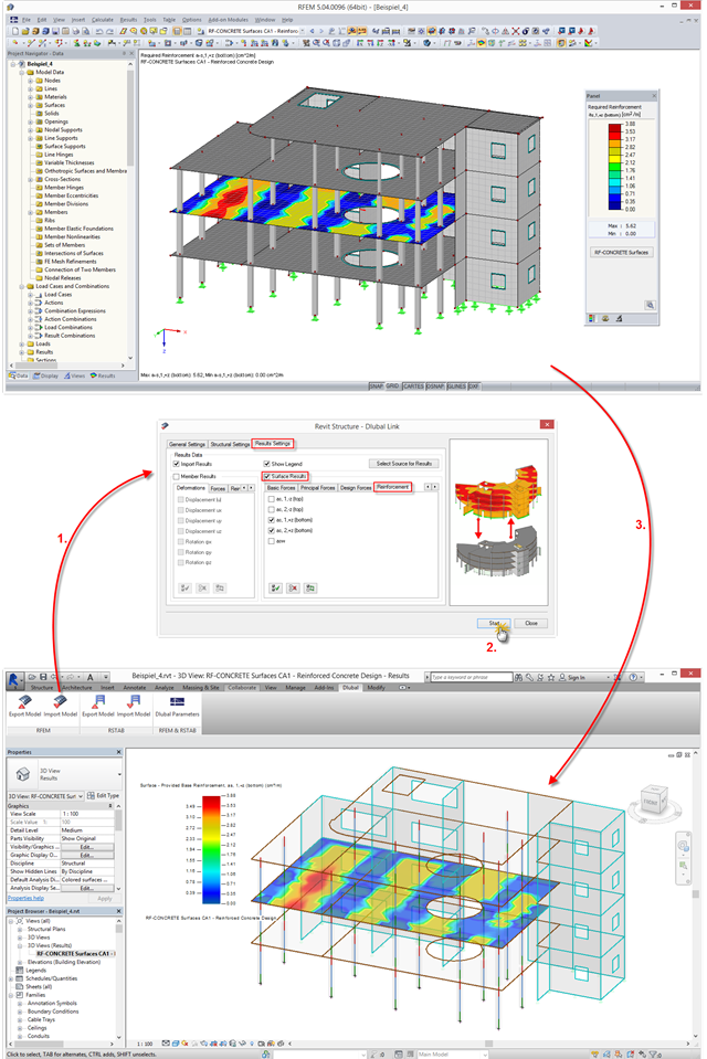
The interface between RFEM/RSTAB and Autodesk Revit has been improved: You can now transfer results from RFEM/RSTAB to Revit and display them there graphically. This option is available in a new tab when importing a file.