Mass Print of Design Components
Technical Article
The add-on modules for designing structural member components according to national, European, and international standards also show design results in addition to numerical output in tables graphically, as diagrams displayed on the framework.
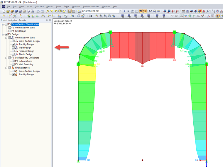
In this case, the Results Navigator controls the logical result components to be considered in the diagrams. For example, the European steel structure design according to EN 1993-1-1 carried out in the RF-/STEEL EC3 add-on module displays designs according to the following categories:
- Ultimate limit state
- Cross-section design
- Stability analysis
- Weld design
- Compression design
- Plastic design
- Serviceability
- Deformation
- Web breathing
- Fire resistance
- Cross-section design
- Stability analysis
This hierarchical display of results is also fully included in the mass print section for report purposes. In the case of a design module, the mass print identifies different design groups in the Results Navigator and provides the corresponding printout options. The options
- "Separate pictures" or
- "Envelope picture"
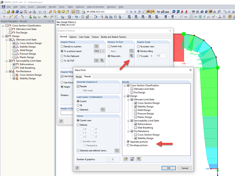
set the course for the information to be displayed in the design graphic. The "Separate pictures" option prints any activated design component as a separate image, and the "Envelope picture" option prints an enveloping result graphic of all design components activated within the option to the selected printout report.
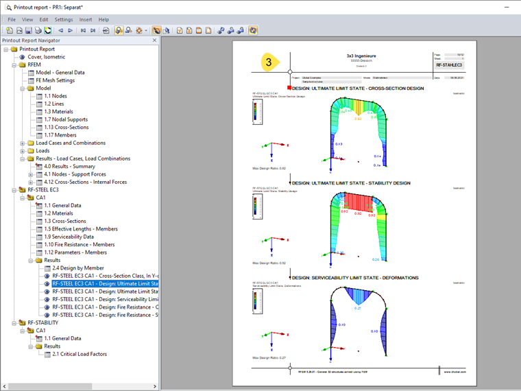
To avoid mistakes, the program shows all considered result components at the top of each result picture. All components used in envelope graphics are mentioned in the graphics accordingly.
Author

Dipl.-Ing. (BA) Andreas Niemeier, M.Eng.
Mr. Niemeier is responsible for the development of RFEM, RSTAB, and the add-on modules for tensile membrane structures. Also, he is responsible for quality assurance and customer support.
Keywords
Mass print Design component Printout report Ultimate limit state Stability Serviceability
Links
Write Comment...
Write Comment...
Contact Us
Do you have any further questions or need advice? Contact us via phone, email, chat or forum or find suggested solutions and useful tips on our FAQ page, available 24/7.

Parametrization of Rolled Cross-Sections
Rolled sections, the most common cross‑section type in RFEM and RSTAB, can also have user‑defined parameters.

Create 3D glTF Models (*.glb and *.glTF Formats)
RFEM and RSTAB models can be saved as 3D glTF models (*.glb and *.glTF formats). View the models in 3D in detail with a 3D viewer from Google or Baylon. Take your VR glasses, such as Oculus, to "walk" through the structure.
You can integrate the 3D glTF models into your own websites using JavaScript according to these instructions (as on the Dlubal website Models to Download).
-
I am trying to import a DXF file. The file can be imported into the model, but it does not have the correct scale. Where is the problem?
- Is the German National Annex 2021‑07 to Eurocode 8 available in RFEM 5 / RSTAB 8?
- How can I permanently save the parameters in the "Units and Decimal Places" dialog box?
- Can I export a response spectrum from RFEM 6 and use it in RFEM 5, for example?
- I have deactivated objects by load case. Why are they still considered in the calculation in the corresponding load case?
- I would like to enter a large spring constant. Is it possible?
- How can I update the graphics driver, and where do I find the current driver versions?
- How can I display the internal forces of a coupling member or rigid member?
- How do I get the current authorization file for RFEM 5, RSTAB 8 and other stand-alone programs?
- Can I also use RWIND 2 with RFEM 5/RSTAB 8?
Associated Products